Mirrors
Definitions
To understand how curved mirrors work, we imagine some test object (usually drawn as an arrow, or a candle) and the test image it forms.
- $d_o$: The distance of the object from the mirror.
- $d_i$: The distance of the image from the mirror.
- $f$: The focal length of the mirror.
- $h_o$: The height of the object.
- $h_i$: The height of the image.
- $M$: The magnification $M=h_i/h_o$.
When drawing optics diagrams with mirrors, we can draw the following three rays:
- $R_\alpha$: A horizontal incoming ray which gets redirected towards
the focus after it hits the mirror.
- $R_\beta$: A ray that passes through the focus and gets redirected horizontally
after it hits the mirror.
- $R_\gamma$: A ray that hits the mirror right in the centre and bounces back
at the same angle at which it came in.
Formulas
The following formula can be used to calculate where an image will be formed, given that you know the focal length of the mirror and the distance $d_o$ of the object: \[ \frac{1}{d_o} + \frac{1}{d_i} = \frac{1}{f}. \]
We follow the convention that distances measured from the reflective side of the mirror are positive, and distances behind the mirror are negative.
The magnification is defined as: \[ M = \frac{h_i}{h_o} = \frac{|d_i|}{|d_o|} \] How much bigger is the image compared to the object?
Though it might sound confusing, we will talk about magnification even when the image is smaller than the object; in those cases we say we have fractional magnification.
Examples
Visual examples
Mirrors reflect light, so it is usual to see an image formed on the same side as where it came from. This leads to the following convention:
- If the image forms on the usual side (in front of the mirror),
then we say it has positive distance $d_i$.
- If the image forms behind the mirror, then it has negative $d_i$.
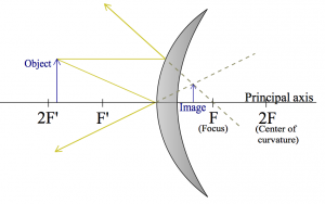
Let us first look at the kind of mirror that you see in metro tunnels: convex mirror. These mirrors will give you a very broad view, and if someone is coming around the corner the hope is that your peripheral vision will be able to spot them in the mirror and you won't bump into each other.
I am going to draw $R_\alpha$ and $R_\gamma$:
Note that the image is “virtual”, since it appears to form inside the mirror.
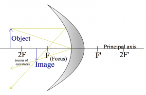
Here is a drawing of a concave mirror instead, with the rays $R_\alpha$ and $R_\gamma$ drawn again.
Can you add the ray $R_\beta$ (through the focus)? As you can see, any two rays out of the three are sufficient to figure out where the image will be: just find the point where the rays meet.
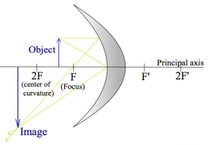
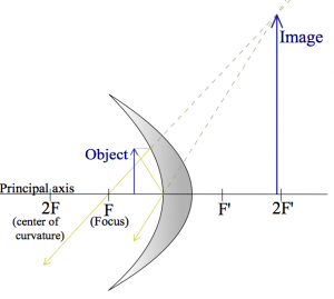
Here are two more examples where the object its placed closer and closer to the mirror.
These are meant to illustrate that the same curved surface, and the same object can lead to very different images depending on where the object is placed relative to the focal point.
Numerical example 1
OK, let's do an exercise of the “can you draw straight lines using a ruler” type now. You will need a piece of white paper, a ruler and a pencil. Go get this stuff, I will be waiting right here.
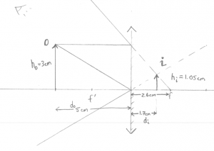
Q: A convex mirror (like in the metro) is placed at the origin. An object of height 3[cm] is placed $x=5$[cm] away from the mirror. Where will the image be formed?
Geometric answer: Instead of trying to draw a curved mirror, we will draw a straight line. This is called the thin lens approximation (in this case, thin mirror) and it will make the drawing of lines much simpler. Take out the ruler and draw the two rays $R_\alpha$ and $R_\gamma$ as I did:
Then I can use the ruler to measure out $d_i\approx 1.7cm$.
Formula Answer: Using the formula \[ \frac{1}{d_o} + \frac{1}{d_i} = \frac{1}{f}, \] with the appropriate values filled in \[ \frac{1}{5} + \frac{1}{d_i} = \frac{1}{-2.6}, \] or \[ d_i = 1.0/(-1.0/2.6 - 1.0/5) = -1.71 \text{[cm]}. \] Nice.
Observe that (1) I used a negative focal point for the mirror since in some sense the focal point is “behind” the mirror, and (2) the image is formed behind the mirror, which means that it is virtual: this is where the arrow will appear to an the observing eye drawn in the top left corner.
Numerical example 2
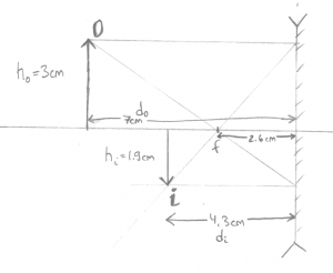
Now we have a concave mirror with focal length $f=2.6cm$ and we measure the distances the same way (positive to the left).
Q: An object is placed at $d_0=7$[cm] from the mirror. Where will the image form? What is the height of the image?
Geometric answer: Taking out the ruler, you can choose to draw any of the three rays. I picked $R_\alpha$ and $R_\beta$ since they are the easiest to draw:
Then measuring with the ruler I find that $d_i \approx 4.3$[cm], and that the image is height $h_i\approx-1.9$[cm], where negative height means that the image is upside down.
Formula Answer: With the formula now. We start from \[ \frac{1}{d_o} + \frac{1}{d_i} = \frac{1}{f}, \] and fill in what we know \[ \frac{1}{7} + \frac{1}{d_i} = \frac{1}{2.6}, \] then solve for $d_i$: \[ d_i = 1.0/(1.0/2.6 - 1.0/7.0) = 4.136 \text{[cm]}. \] To find the height of the image we use \[ \frac{h_i}{h_o} = \frac{d_i}{d_o}, \] so \[ h_i = 3 \times \frac{4.136}{7.0} = 3 \times 4.13/7.0 = 1.77 \text{[cm]}. \] You still need the drawing to figure out that the image is inverted though.
Generally, I would trust the numeric answers from the formula more, but read the signs of the answers from the drawing. Distances in front of the mirror are positive whereas images formed behind the mirror have negative distance.
