The page you are reading is part of a draft (v2.0) of the "No bullshit guide to math and physics."
The text has since gone through many edits and is now available in print and electronic format. The current edition of the book is v4.0, which is a substantial improvement in terms of content and language (I hired a professional editor) from the draft version.
I'm leaving the old wiki content up for the time being, but I highly engourage you to check out the finished book. You can check out an extended preview here (PDF, 106 pages, 5MB).
Magnetic induction
In the previous section we learned about the magnetic field, how it is caused by current carrying wires and its effects on other current carrying wires. In this chapter we will learn how a changing magnetic fields can produce an electromotive force – how changing currents in one wire can induce a current in another wire.
Note that magnetic field has to be changing in order to produce induced voltages and an induced currents. A constant currents produces a constant magnetic field and a constant magnetic fields does not induce currents. This is a very important to keep in mind.
In this section we will study Faraday's law of induction. It states that any change in the total magnetic field flowing through some winding will cause an induced current to flow in the winding as a result. This is a special case of the more general Le Chatelier principle since the induced current will flow in such a direction as to produce a oppose magnetic field and counter act the external change.
Concepts
- $\mu_0$: the magnetic constant, or permeability of free space. It is equal to
$4\pi\times10^{-7}$ [Vs/Am] = $1.2566\times10^{-6}$ [H/m]=[N/A^2]
- $\vec{B}$: Magnetic field strength and direction.
- $\mathcal{E}\equiv V_{\mathcal{E}}$: Induced electric potential (induced voltage)
in the winding. It is also known as the electromotive force.
- $I_{\mathcal{E}}$: Induced electric current. The induced current in a winding of
resistance $R$[$\Omega$] will be $I_{\mathcal{E}}=\mathcal{E}/R$.
- $S$: some surface in space. ex: $S$=the area enclosed by a loop of wire.
- $\Phi_S$=The magnetic flux through $S$, i.e., how much magnetic
filed $B$ passes through the surface $S$. We have $\Phi_S = \vec{B} \cdot \vec{S}$,
  where $\vec{S}$ is the oriented surface area.
* $N$: Number of loops in a winding. Each turn of wire in the winding produces and
  reacts to the magnetic field. The induced voltage in a winding with $N$ turns
  is $N$ times stronger than that induced in a single loop of wire.
Formulas
Magnetic flux
Consider the surface $S$ and let $\hat{n}$ be a vector that is perpendicular to the surface (the normal vector). The directed surface is given by $\vec{S}=S\hat{n}$.
The magnetic flux is given by: \[ \Phi_S = \vec{B} \cdot \vec{S} = |\vec{B}|S \cos \theta, \] where $\theta$ is the angle between the normal vector of the surface $S$ and the orientation of the magnetic field. The flux measures of how many magnetic field lines flow through the surface. If the magnetic field flows perpendicularly to the surface then $\theta=0$ and $\Phi_S = |\vec{B}|S$. On the other hand, if the magnetic field is parallel to the surface, then $\theta=90^\circ$ and there is zero magnetic flow through the surface.
Faraday's law of induction
Consider a loop of wire and let $S$ represent the area enclosed by this loop. Faraday's law states that any change in the magnetic flux through that loop will produce an induced voltage (an electromotive force) on all electrons in the wire. The magniture of this induced voltage is given by the formula: \[ \mathcal{E} = - \frac{d \Phi_S}{dt}. \] The negative sign is there to remind you that the induced voltage will always act in a opposite direction to the change in the flux.
Example: Changing B
Suppose you have a loop of wire with area $A=5$[m$^2$] in a place this loop in a location where an upward magnetic field exists, which is slowly increasing in time: \[ \vec{B}(t) = (0,0, 3t) = 3t \hat{k}. \] Every second the magnetic field will become stronger by $3$[T].
Faraday's law tells us that the changing magnetic field will induce a voltage (electromotive force) in the loop that is equal to \[ \mathcal{E} = - \frac{d \Phi_S}{dt} = - \frac{d}{dt} \left( \vec{B}(t)\cdot\vec{A} \right) = - \frac{d}{dt} \left( 3t \hat{k} \cdot A\hat{k} \right) = A \frac{d}{dt}\left( 3t \right) = 15 [V]. \] The effects of the induced voltage $\mathcal{E}$ in the loop is equivalent to connecting a $15$[V] battery somewhere in the loop.
If the electric resistance of the loop of wire is 10[$\Omega$], then the induced current will be 1.5[A]. This current will flow in the clockwise direction when looked from above. This is because the induced current is trying to counteract the increasing and upward pointing magnetic field by causing a downward magnetic field.
Observe that the value of the magnetic field was not important in this context: only the derivative of the field mattered. The answer would have been the same if we had $\vec{B}(t) = (3t + 3000)\hat{k}$, because the derivative of a constant is zero.
Generators
Consider now a constant magnetic field $\vec{B}$ and wire winding of area $A$[m$^2$] mounted on an axis so that it can rotate. Such a construction could serve as a rudimentary electric generators: a device which transforms rotational mechanical energy into electric energy.
The magnetic flux through the winding will be given by: \[ \Phi_S = N \vec{B} \cdot \vec{A} = NBA \cos(\theta), \] where $N$ is the number of turns in the winding and $\theta$ describes the orientation of the winding relative to the constant magnetic field.
If we use an external force to make the winding rotate at a constant speed $\omega$ then the magnetic flux as a function time will be: \[ \Phi_S(t) = NBA \cos(\omega t + \theta_0). \]
The induced voltage that we would be able to read if we were to put a voltmeter on the two ends of the turning winding would be: \[ \mathcal{E}(t) = - \frac{d \Phi_S(t) }{dt} = - \frac{d}{dt}\left( NBA \cos(\omega t + \theta_0) \right) = NBA\omega \sin(\omega t + \theta_0). \]
This is an alternating voltage, that keeps changing from positive to negative depending on the relative orientation of the loop in the magnetic field. This is how Hydro Quebec generates power. With big generators.
Electric motor
A generator can also be used backwards: the same device can also be used to convert electric energy into mechanical energy. Used in that direction, the rotating winding construction is called an electric motor.
A motor has two parts. The stator, which in our case is the constant background magnetic field $\vec{B}$ and a rotor, which is our rotating winding.
If we use electric energy to make a current flow in the winding, then the winding will produce its own magnetic field and the interaction between the two B-fields will cause the winding to turn.
Transformers
If you put two windings close to each other and put an make and alternating current flow in one of the windings, we will immediately see an induced alternating current in the second winding. This device is called a transformer. We will learn about these in more detail in the chapter on alternating currents.
Self inductance
Consider a solenoid of cross section area $A$ and winding density $n = N/L$ which has a current $i(t)$ flowing in the wire.
We learned in the last section that a current $i(t)$ flowing in the solenoid will produce a magnetic field inside the device and we know that the formula is given by: \[ |\vec{B}| = \mu_0 n i(t). \]
We learned in this section that any winding will react to a change in the magnetic flux through it by producing an induced voltage. Since a solenoid is a winding, so it will react to any changes in the magnetic field which would appear if the current were changing in time. The formula for the induced voltage is: \[ \mathcal{E} = - \frac{d \Phi_S(t) }{dt} = - \frac{d (AN|\vec{B}|) }{dt}, \] where we used the fact that the magnetic field everywhere inside an inductor is constant and that each of the $N$ windings contribute to the total induced voltage.
Combining these formulas we see that \[ \mathcal{E} \equiv v(t) = - \frac{d (AN|\vec{B}|) }{dt} = - \underbrace{AN\mu_0 n}_L \frac{d i(t)}{dt} = - L \frac{d i(t)}{dt}, \] where we have lumped together all the constants into a single one $L$.
This solenoid, and in general all windings, exhibit this phenomenon of self-inductance where the chaining current in the winding cause an induced voltage.
In circuits we call such devices inductors and they are in some sense the dual of the capacitor in which it was the changing voltage that caused a current. The constant $L$ is called the inductance or self-inductance of the device.
Examples
Example 1: Area changing
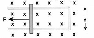
 Consider the external force $\vec{F}$ that is dragging
the bar along with velocity $\vec{v}$. If the magnetic field
everywhere is given by $\vec{B}$ and points into the page.
What is the change of flux $\frac{d \Phi_S(t) }{dt}$ ?
What is the induced voltage? Will the induced current flow in the clockwise or counter-clockwise direction when looked from above?
Example 2: Strength changing
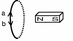
If the magnet is moved away from the loop, what will be the induced current in the loop?
- none
- a
- b
explain
Discussion
Links
[ More on Faraday's law of from HyperPhysics ]
http://hyperphysics.phy-astr.gsu.edu/hbase/electric/farlaw.html
http://hyperphysics.phy-astr.gsu.edu/hbase/magnetic/fluxmg.html
[ Ilustrations of magnetic induction ]
http://web.mit.edu/8.02t/www/802TEAL3D/visualizations/faraday/index.htm

