The page you are reading is part of a draft (v2.0) of the "No bullshit guide to math and physics."
The text has since gone through many edits and is now available in print and electronic format. The current edition of the book is v4.0, which is a substantial improvement in terms of content and language (I hired a professional editor) from the draft version.
I'm leaving the old wiki content up for the time being, but I highly engourage you to check out the finished book. You can check out an extended preview here (PDF, 106 pages, 5MB).
Capacitors
Capacitors are used to store electric energy. We can also call them condensers, since they condense a lot of charge in one place. We saw already that the capacity of an object to store electric charge is proportional to the surface area the object. To store a lot of charge, therefore, you need large objects, but it is impractical to carry around huge metallic spheres.
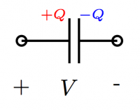 A more successful way to store charge is the parallel
plate capacitor which has two plates: one side will
store positive charge and the other negative charge.
We can imagine that some a voltage source of $V$[V] is
used to charge the capacitor by stripping electrons
from the (+) side and moving them over to the (-) side.
When the capacitor is disconnected, it will then store
the charge $+Q$ and $-Q$ on its plates.
The capacitance, $C$[F], is a property of the capacitor
which tells us how much charge it will store for a
given voltage $V$ applied to it: $Q=CV$.
Inside every camera there is a simple electronic circuit that uses a capacitor in order to provide a sudden burst of electricity to the light bulb. When you turn on the flash, the circuit starts by connecting the capacitor to the battery in order to charge the capacitor. If your camera uses two AA batteries, then the charging voltage will be 3[V]. During this time, a blinking yellow light will indicate to you that you should wait. The camera is saying “Wait a minute please while I pump some charge into the capacitor”. When the charging is done and you take the picture, all the electric energy stored in the capacitor will be released in one burst (a current spike) into the flash lightbulb thus resulting in moment of super high light intensity unlike one that would be possible if you simply connected the light bulb to the batteries.
Concepts
- $Q$: The amount of charge on the capacitor. The (+) plate will have charge $+Q$[C],
while the (-) plate will have $-Q$[C].
- $V$: The voltage access the capacitor.
- C: the capacitance of the capacitor.
For a parallel plate capacitor, the capacitance $C$ is a function of the following physical properties of the capacitor:
- $A$: the area of the plates.
- $d$: the distance between the plates.
- $\varepsilon=\varepsilon_r\varepsilon_0$: The permittivity of the material between the plates,
where $\varepsilon_0$ is the permittivity of free space and $\varepsilon_r$ is the relative permittivity
of the material.
We will also study the electric potential ($V$) and the electric field $\vec{E}$ at different points in the capacitor:
- $x$: a variable that indicates the distance from the (+) plate inside the capacitor. $x\in[0,d]$.
- $V(x)$: the voltage (electric potential) in the capacitor at position $x$.
- $\vec{E}(x)$: the electric field at position $x$ inside the capacitor.
To study the process of charging and discharging, we must describe the state of the capacitor as a function of time:
- $q(t)$: the charge on the (+) plate as a function of time.
- $v_c(t)$: the voltage between the plates of the capacitor as a function of time.
- $i_c(t)$: the current entering the (+) side of the capacitor.
Formulas
Definition of capacitance
The charge stored on a capacitor of capacitance $C$[F] when charged to a voltage $V$[V] is given by: \[ Q = CV. \] The units of capacitance are Farads [F]=[C/V].
Physics properties
Consider a capacitor of area $A$, plate separation $d$ and material of dielectric constant $\varepsilon$ inserted between the plates. The capacitance of such a device is \[ C = \frac{\epsilon A}{d}. \qquad [\textrm{F}] \]
Voltage-current relationship
Because charge cannot simply be created from thin air, any amount of charge that appears on the (+) plate must have come into the capacitor as an electric current of charge. We define the current entering the capacitor $i_c(t)$ as the derivative of the charge on in the capacitor: \[ i_c(t) \equiv \frac{dq(t)}{dt}. \qquad [\textrm{A}] = [\textrm{C}/\textrm{s}] \] The bigger the current flowing into the (+) side of the capacitor, the faster the charge will build up. By using the definition of capacitance $Q=CV$, we also get the following relation \[ i_c(t) = C \frac{dv_c(t)}{dt}, \] which relates $i_c(t)$ and $v_c(t)$ the two quantities which we usually measure in circuits.
Another way of looking at the above differential relation is to say that the charge on the plate, $q(t)$, is equal to the initial charge $q(0)$ plus the sum (integral) of all the current that has gone into the capacitor: \[ q(t) = q(0) \ + \ \int_0^t i_c(\tau) d\tau. \] We can use the relation $Q=CV$ rewritten as $V=\frac{1}{C}Q$ to obtain the equation: \[ v_c(t) = v_c(0) \ + \ \frac{1}{C}\int_0^t i_c(\tau) d\tau. \]
Recall from calculus that a necessary condition for a function to have a well defined derivative is for the function to be continuous. The fact that we have $i_c(t) = C \frac{dv_c(t)}{dt}$ means that the capacitor voltage $v_c(t)$ must be continuous: it cannot suddenly jump in value or else this would correspond to infinite amount of current, which is impossible. Because of this voltage-smoothing property of capacitors, they are used in electronics and sound equipment in order to filter out voltage spikes.
Energy stored in a capacitor
The energy stored in a capacitor is given by \[ E = \frac{1}{2} Q V = \frac{1}{2} \frac{Q^2}{C} = \frac{1}{2} CV^2. \qquad [\textrm{J}] \]
Equivalent capacitors
We will now study what happens if we connect multiple capacitors together. We will see two formulas for finding the equivalent capacitance of the capacitors taken together as a whole.
Capacitors in parallel
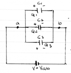 If you take several capacitors and connect them to the
same voltage source we get the parallel configuration.
In this setup, all the capacitors will have the same voltage
across their plates:
\[
V_1 = V_2 = V_3 = V_{ab}.
\]
Effectively, you have build a
capacitor that has a combined surface area of the
three capacitors.
It should not be a surprise that the formula for
the equivalent capacitance of the three capacitors
taken together is
\[
C_{eq} = C_1 + C_2 + C_3.
\]
Furthermore, because we know the voltage on each of the capacitors is $V_{ab}$ we can use $Q=CV$ to find the charge on each of the capacitors: \[ Q_1 = C_1 V_{ab}, \qquad Q_2 = C_2 V_{ab}, \qquad Q_3 = C_3 V_{ab}. \]
Capacitors in series
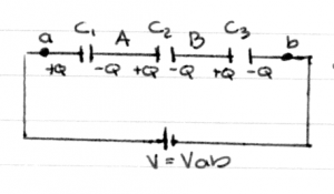 Consider now three capacitors connected one after the other.
We say that the capacitors are connected in series.
Consider the region labelled (A), which consists
of the (-) plate of $C_1$ and the (+) plate of $C_2$.
Because the region (A) started off initially uncharged,
it must be so after the battery is connected. Whatever
negative charge exists on the (-) plate of $C_1$,
therefore, must have comes from the (+) plate of $C_2$.
The same is true for the region (B).
This means that the charge on all the capacitors must
be the same:
\[
Q_1 = Q_2 = Q_3 = Q.
\]
Since the capacitors are connected in series, the battery voltage $V_{ab}$ must be shared between all the capacitors. By Kirchhoff's voltage rule we have that: \[ V_{ab} = V_1 + V_2 + V_3. \]
We can now use the relationship $V=Q/C$ to obtain: \[ V_{ab} = \frac{Q}{C_1} +\frac{Q}{C_2} + \frac{Q}{C_3}. \] The effective capacitance $C_{eq} = \frac{Q}{V_{ab}}$ can therefore be calculated as follows: \[ C_{eq} = \frac{Q}{V_{ab}} = \frac{Q}{ \frac{Q}{C_1} +\frac{Q}{C_2} + \frac{Q}{C_3} } = \left( \frac{1}{C_1} +\frac{1}{C_2} + \frac{1}{C_3} \right)^{-1}. \] The last equation is called the harmonic sum, and also appears when calculating the equivalent resistance of resistors connected in parallel. The series and parallel addition formulas for capacitors and resistors are opposite.
Electric field inside a capacitor
Recall from the section on the electric_field that there is a relationship between the strength of the electric field $\vec{E}$ and the electric potential $V$. The voltage $V({r})$ at a point $r$ is defined as the integral per unit charge of the work you would have to do to bring a test charge to the point $r$. Because $\vec{E}({r})$ corresponds to the force per unit charge, we obtained the following relation: \[ V({R}) = - \int_{\infty}^R \vec{E}({r}) \cdot d\vec{s}, \] where $d\vec{s}$ describes the steps of the path which we took to bring the charge to the point $R$.
In this section we will use the differential version of the above relationship: \[ \vec{E}({r}) = - \; \frac{dV({r})}{ dr }, \] which states that the electric field is the gradient (derivative in space) of the electric potential.
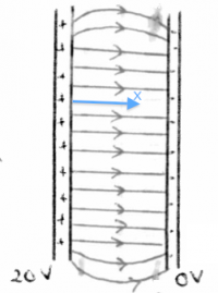 Consider the capacitor shown on the right,
which has a voltage of 20[V] between its (+) plate
and its (-) plate.
Using the (-) plate as a potential reference,
we can say that the voltage at (-) is 0[V],
and that the voltage at (+) is 20[V].
Assuming the material between the plates is uniform,
the voltage between the plates must vary continuously
as we go from one plate to the other.
The electric potential inside the capacitor is
\[
V(x) = 20 - \frac{20}{d}x,
\]
where $d$ is the plate separation and $x$ is a coordinate
which measures the distance from the (+) plate.
Check that $V(x)$ gives the correct potential at $x=0$ and
$x=d$.
The strength of the electric field inside the capacitor is therefore given by the derivative of the voltage with respect to $x$: \[ \vec{E}(x) = - \frac{d}{dx} V(x) = \frac{20}{d}. \qquad [\textrm{V}/\textrm{m}] \]
We generally report the units of electric field as $[\textrm{V}/\textrm{m}]$ instead of the equivalent $[\textrm{N}/\textrm{C}]$. This is an indicator of the fact that relationship $\vec{E}(x) = - \frac{d}{dx} V(x)$ is used more often than the relationship between $\vec{F}_e = q\vec{E}$ in practice.
Charging and discharging
The currents and voltages associated with the process of charging and discharging a capacitor can be described mathematically. In this section we will find the equation for the current $i_c(t)$ as a function of time by using principles from circuits and solving a simple differential equation.
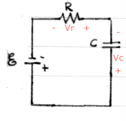 Consider a circuit which connects a battery, a capacitor and a resistor.
This is called an RC circuit.
The voltages across each of the elements have been indicated.
By Kirchhoff's voltage law (KVL) the voltage gains/drops
in this loop must add up to zero so we have:
\[
+ V_{\mathcal{E}} - v_c - v_r = 0.
\]
We now rewrite this equation in terms of the current $i(t)$ that will flow around the loop. We know that the voltage of a resistor is $v_r(t) = Ri(t)$ and we also know that $v_c(t)=\frac{1}{C}\int i(t) dt$, so the equation becomes: \[ + V_{\mathcal{E}} - \frac{1}{C}\int i(t) dt - Ri(t) = 0. \]
Now we take the derivative of this equation to obtain \[ + 0 - \frac{1}{C}i(t) - Ri'(t) = 0, \] where the first terms is zero because $V_{\mathcal{E}}$ is constant and the second term follows from the fundamental theorem of calculus (the derivative is the inverse operation of the integral).
We still haven't found $i(t)$ but we know that it must obey the following differential equation: \[ i'(t) = -\frac{1}{RC}i(t). \]
Can you think of any function $f(x)$ which is equal to the negative of its derivative up to a constant? The only function which has this property is of the form $f(x) = \alpha e ^{-\beta x}$, where $\beta > 0$ and $\alpha$ is an arbitrary constant.
By choosing the constant in the exponent appropriately, namely $\beta = \frac{1}{RC}$, we obtain the formula for the current in the circuit as a function of time \[ i(t) = \alpha e^{-\frac{t}{RC}}. \] Check that this function satisfies the differential equation $i'(t) = -\frac{1}{RC}i(t)$.
Now that we have the current $i(t)$ in the circuit, we can calculate the voltage of the capacitor by integration: \[ v_c(t) = \int i(t) dt = \beta e^{-\frac{t}{RC}} + \gamma, \] where $\beta=-\alpha RC$ and $\gamma$ is an arbitrary constant of integration.
We now discuss how to set the constants $\beta$ and $\gamma$ in the above equation so that it will describe the charging and discharging voltage of a capacitor.
Charging capacitor
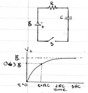 Consider capacitor of capacitance $C$ being charged
by a battery of $V_{\mathcal{E}}$ volts through a resistance
of $R$ ohms as illustrated in the circuit on the right.
We want to find the equation of
the voltage of the capacitor as a function of time.
We know that the general formula for the voltage in an RC circuit is given by \[ v_c(t) = \beta e^{-\frac{t}{RC}} + \gamma, \] so we have to just choose the constants $\beta$ and $\gamma$ appropriately by taking into account the boundary conditions. The first boundary condition is at $t=\infty$, when the capacitor will have fully charged to the voltage of the battery $V_{\mathcal{E}}$. Using this fact we can deduce that $\gamma=V_{\mathcal{E}}$ from the equation \[ v_c(\infty) = V_{\mathcal{E}} = \beta e^{-\frac{\infty}{RC}} + \gamma =\beta \times 0 + \gamma = \gamma. \]
The second boundary condition (we need two since there are two unknown constants) is that the capacitor starts completely discharged. Thus, when we close the switch at $t=0$, the initial voltage on the capacitor is $v_c(0)=0$. We can now use the equation \[ v_c(0) = 0 = \beta e^{-\frac{0}{RC}} + \gamma = \beta \times 1 + \gamma = \beta + \gamma \] and our previous findings that $\gamma=V_{\mathcal{E}}$ to deduce that $\beta=-V_{\mathcal{E}}$.
The function describing the voltage of a charging capacitor as function of time is therefore given by: \[ v_c(t) = V_{\mathcal{E}} - V_{\mathcal{E}} e^{-\frac{t}{RC}} =V_{\mathcal{E}} \left[ 1 - e^{-\frac{t}{RC}} \right]. \]
Recalling that $i_c(t) \equiv C\frac{dv_c(t)}{dt}$ we can also derive the current of the capacitor \[ i_c(t) = C\frac{d}{dt}\left[ V_{\mathcal{E}} - V_{\mathcal{E}} e^{-\frac{t}{RC}} \right] = \frac{V_{\mathcal{E}}}{R} e^{-\frac{t}{RC}}. \] The constant $\frac{V_{\mathcal{E}}}{R}=i_c(0)$, which we previously called $\alpha$, corresponds to the maximum charging current that will flow in the circuit.
Discharging capacitor
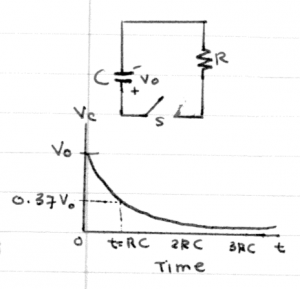 Consider now a capacitor charged to voltage $V_o$ which
discharges into a resistor of resistance $R$ starting at $t=0$,
when the switch is closed.
We start off from the general equation again \[ v_c(t) = \beta e^{-\frac{t}{RC}} + \gamma. \] The boundary conditions in this case are that the initial voltage $v_c(0)=V_o$ and the final voltage $v_c(\infty)=0$, which corresponds to the time when the capacitor has discharged completely. By plugging in the boundary conditions into the general equation we find that $\beta=V_o$ and $\gamma=0$. The equation for the voltage of a discharging capacitor is: \[ v_c(t) = V_o e^{-\frac{t}{RC}}. \]
We can also find the value of the capacitor current: \[ i_c(t) = C \frac{d}{dt} v_c(t) = -\frac{V_o}{R} e^{-\frac{t}{RC}}. \] The maximum discharge current is given by $-\frac{V_o}{R}=i_c(0)$. The negative sign indicates that the current is leaving the (+) plate of the capacitor.
In both of the above scenarios, the parameter $\tau=RC = \frac{1}{\beta}$ describes the time scale for the capacitor to charge or discharge. We call this quantity the time constant and measure it in seconds [s]. When charging, the time constant tells us how long it takes the capacitor to charge to $63\%=0.63=1-e^{-1}$ times its maximum voltage $V_{\mathcal{E}}$. When discharging, the time constant $\tau$ tells us how long it will take for the capacitor to reach $37\%=0.37=e^{-1}$ of its initial voltage $V_o$.
Explanations
Voltage continuity
The relationship between the current $i_c(t)$ and the voltage $v_c(t)$ is the defining features of a capacitors. More generally, we say that any circuit element is capacitive if the current of the device is proportional to the derivative of the voltage.
Capacitor energy derivation
We can equate the energy stored in a capacitor with the total energy consumed by the capacitor as while it charges up.
Consider some small amount of charge $dq$ which we want to add to the capacitor. The energy associated with moving this charge is given by $dE = dq v_c(t)$. This comes from the definition of power $\frac{dE}{dt} \equiv P(t) =i_c(t)v_c(t)$ and identifying the movement of charge $dq$ as the amount of current $i_c(t)=\frac{dq}{dt}$.
The total energy stored in the capacitor is calculated by taking the integral over the variable $q$. We sum up the individual contributions $dE$ for each of the $dq$s as the capacitor goes from $q=0$ to $q=Q$. \[ E = \int_{q=0}^{q=Q} v_c(q) \ dq = \int_{q=0}^{q=Q} \frac{q}{C} \ dq = \frac{1}{C} \frac{q^2}{2} \bigg|_{q=0}^{q=Q} = \frac{1}{2} \frac{Q^2}{C}. \] The other forms of the energy equation are obtained by using $Q=CV$.
Exercises
1. Capacitor charge
You are given a 5 [mF] capacitor and asked to produce a charging circuit which will charge the capacitors to 97% of the maximum voltage in 3[s]. What value should you use for the resistor?
2. Diff that for me will you?
Using a voltmeters, you observe that the voltage across a capacitor of capacitance $7$[$\mu$F] varies as the function $v_c(t) = 7\sin(120\pi t)$ [V]. What is the equation of current $i_c(t)$?
