The page you are reading is part of a draft (v2.0) of the "No bullshit guide to math and physics."
The text has since gone through many edits and is now available in print and electronic format. The current edition of the book is v4.0, which is a substantial improvement in terms of content and language (I hired a professional editor) from the draft version.
I'm leaving the old wiki content up for the time being, but I highly engourage you to check out the finished book. You can check out an extended preview here (PDF, 106 pages, 5MB).
Circuits
Electric circuits are contraptions in which electric current flows through various pipes (wires) and components (resistors, capacitors, inductors, on-off switches, etc.). Because the electric current cannot escape the wire, it is forced to pass through each of the components along its path.
Your sound system is a circuit. Your computer power supply is a circuit. Even the chemical reactions involved in neuronal spiking can be modelled as an electric circuit.
Concepts
$I$: the electric current. It flows through all circuit components. We measure current in Amperes $[A]$.
  We use wires to guide the flow of currents: to make them go where we want.
* {{ :electricity:circuit-element-voltage.png|}}
  $V$: the electric potential difference between two points. We say //voltage// for short instead of "electric potential difference". There is no notion of "absolute" voltage, we only measure potential difference between //two// points. Thus if you should always label a (+) side and a (-) side when reporting a voltage. Conveniently, the unit of Voltage is the Volt [V], after Volta.
* $P$: the power consumed or produced by some component. Measured in Watts [W].
* $R$: the //resistance// value of a resistor. For resistors, the voltage across the leads is linearly related to current flowing in the resistor. We call //resistance// the ratio between the voltage and the current:
  \[
    R=\frac{V}{I}.
  \]
  We measure resistance in Ohms [$\Omega$].
Circuit components
The basic building blocks of circuits are called electric components. In this section we will learn how to use the following components.
\[ V_{\text{wire}} = \text{any}, \quad \qquad I_{\text{wire}} = \text{any} \]
Battery: This is a voltage source. Can provide any current, but always keeps a constant voltage of V volts.
  \[
    V_{\text{batt}} = V, \qquad \qquad I_{\text{batt}} = \text{any}
  \]
Current source: This device pushes a constant current of $I$ [A], no matter what circuit it is connected to. The current source is allowed to have any voltage across its terminals.
  \[
    V_{\text{source}} = \text{any}, \quad \qquad I_{\text{source}} = I
  \]
Resistor: Can carry any current $I$, and has a voltage across its terminals of $V=RI$ where $R$ is the resistance measured in Ohmns [$\Omega$].
  \[
    V_{\text{resistor}} = I_{\text{resistor}}R, \qquad \qquad I_{\text{resistor}} = \frac{V_{\text{resistor}}}{R}
  \]
  The energy of the electrons (the voltage) right before entering the resistor is $IR$ [V] higher than when they leave the resistor. It is important to label the positive and negative terminals of the resistor. The positive terminal is where the current enters, the negative where the current leaves.
An on-off switch.
  When the switch is //off// (we also say //the switch is open// like in the figure on the right),
  then the two pieces of wires are disconnected and no current is allowed
  to flow through.
  When the switch is //on// (or //closed//), then it acts like a piece of wire
  and will let current through.
General principles
Ohm's law
The voltage across the terminals of a resistor is proportional to the current
flowing through. The more current flowing through, the more voltage will be dropped.
The constant of proportionality is called resistance of the element.
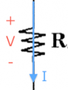 \[
V= IR, \qquad \text{or} \qquad I = \frac{V}{R}, \qquad \text{or} \qquad R = \frac{V}{I}
\]
This is obey Ohm's law.
Electric power
The power consumed by an electric component is given by \[ P = V I, \] where $I$ is the current going into the (+) terminal of the device. The logic behind this formula is as follows. Each electron passing through the device will have lost $V$ volts of electric potential by passing through the device, and the more of them that are flowing (high current) then more power will be consumed.
For batteries, usually the current leaves the (+) terminal instead of entering it, which is equivalent to saying that a negative current flows into the (+) terminal. The expression for the power consumed will therefore be negative: which makes sense since batteries supply energy to the circuit.
For resistors, the current always flows into the (+) side, so power is always consumed. Furthermore, since we know that $V=IR$, we can rewrite the power formula in two other equivalent forms: \[ P = V I, \qquad P = \frac{V^2}{R} \qquad P = RI^2. \] These forms are useful when only the current or the voltage of a resistor is known.
Kirchhoff's loop law
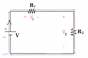 Let's follow the life of a charge going around in the circuit.
It's kind of like a reality show, but with a really simple character.
The journey of the charge begins at $\color{blue}{\text{start}}$, and we will say that the electric potential of this point is $0$[V].
The charge goes up and as it passes through the battery it gains $V$ volts of potential.
We know this, because this is what batteries do: they take charges at the (-) terminal and push them out of (+) terminal with $V$ volts more electric potential.
Next the charge goes right and passes through the resistor $R_1$. The result of this is a change of $-V_1$ in electric potential. This is because the charge dissipated some energy as it passed thought the resistor.
Some more voltage is dropped as it passes through the second resistor. The change in potential is $-V_{2}$,
because the change enters the (+) side and leaves at the (-) side.
Then the charge comes back to $\color{blue}{\text{start}}$, and so its potential must be zero again:
\[
0 + V - V_1 - V_{2} = 0.
\]
By doing this imaginary journey we have established a connection between the battery voltage and the total voltage dropped in the circuit loop.
Kirchhoff's law says that the sum of the voltage gains and drops along any loop must add up to zero: \[ \sum_{\text{loop}} V_i = 0. \]
Kirchhoff current law
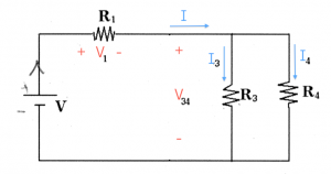
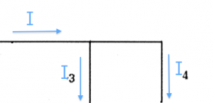 If you have one current going into a junction, and two currents leaving the junction then:
\[
I = I_3 + I_4.
\]
This is implied by conservation of charge: charge can't be created or destroyed so the sum of the currents coming into a junction, must equal the sum of the currents leaving the junction:
\[
\sum I_{\text{in}} = \sum I_{\text{out}}.
\]
Resistances in series
 If you have several resistors attached together in series, then the
equivalent resistance of the three resistors is
\[
R_{eq} = R_1 + R_2 + \ldots + R_n.
\]
Note that in this configuration the same current flows through all the resistors.
Example 1
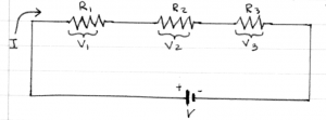 Suppose you have connected three resistors $R_1=1[\Omega]$, $R_2=3[\Omega]$ and $R_3=5[\Omega]$ in series to a 16[V] battery.
Q: What is the equivalent resistance of the circuit?
A: The equivalent resistance that the battery sees is $R_{eq}=R_1+R_2+R_3 = 8[\Omega]$.
Q: What will be the current $I$ in the circuit?
A: The current flowing in the circuit can be found by using Ohm's law V=IR. In this case $I=\frac{V}{R}=\frac{16}{8} = 2$[A].
Q: What is the voltage drop across $R_3$?
A: The voltage is $V_3=IR_3=(2[A])(5[\Omega]) = 10$[V].
Resistances in parallel
 For resistors in parallel, the equivalent resistance is:
\[
R_{eq} = \frac{1}{\frac{1}{R_1}+\frac{1}{R_2}+\ldots+\frac{1}{R_n}}.
\]
Because all the resistors are connected to the same (+) and (-)
endpoints, they will all have the same voltage across them.
When there are just two resistors in parallel, the equation simplifies to: \[ R_{eq} = \frac{1}{ \frac{1}{R_1}+\frac{1}{R_2} } = \frac{R_1R_2}{R_1+R_2}. \] We sometimes denote the equivalent resistance of $R_1$ and $R_2$ in parallel as $R_1 \| R_2$.
Example 2
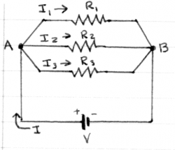 Suppose you have connected three resistors $R_1=1[\Omega]$, $R_2=3[\Omega]$ and $R_3=5[\Omega]$ in parallel to a 16[V] battery.
Q: What is the equivalent resistance of the circuit?
A: The equivalent resistance as seen by the battery is: $R_{eq}=\left(\frac{1}{1}+\frac{1}{3}+\frac{1}{5}\right)^{-1}$.
We can calculate it by finding the least common denominator.
$R_{eq} = \left(\frac{15}{15}+\frac{5}{15}+\frac{3}{15}\right)^{-1} =
\left(\frac{23}{15}\right)^{-1}=\frac{15}{23}\approx 0.652[\Omega]$.
Q: What will be the current $I$ drawn from the battery?
A: The battery will supply $I=\frac{V}{R_{eq}}$ Amperes.
In this case $I=\frac{V}{R}=\frac{16}{15/23} = 368/15\approx 24.533$[A].
Q: What are the currents $I_1$, $I_2$ and $I_3$ flowing through each resistor?
A: All three resistors are connected across the same voltage $V=16$[V], so we can use Ohm's law on each individually to find the current. $I_1 = \frac{16}{1}=16$[A], $I_1 = \frac{16}{3}\approx 5.333$[A],
and $I_3 = \frac{16}{5}=3.2$[A]. Note that $I_1+I_2+I_3=I$ as required by Kirchhoff's current law for points A and B.
Q: What is the voltage drop across $R_3$?
A: This is a trick question. $R_3$ is connected across the $16$[V] battery, so the voltage drop across it is 16[V].
Units
I want to also give you some intuition about the quantities we normally see in circuit. Most electronics work with milliamperes [mA] and small voltages like 3V or 5V. On the other hand, an electric radiator can draw about 10$[A]$ or current easily. The voltage that is used for power transport over long distances is on the order of 50000$[V]$ – this is why they call them high-voltage lines.
Worked example
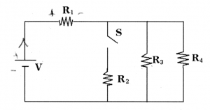
You have in your hands the following circuit. There is a voltage source of $V$[V] and four loads $R_1$, $R_2$, $R_3$ and $R_4$, which could be light bulbs, heating elements or any other kind of device. Assume that the value of the resistances are given to you and you are given the following task: Find the value of of the current flowing through resistor $R_4$?
First observe that the switch $S$ is open, so effectively that entire branch of the circuit is completely disconnected and we can ignore it. We have to find all the currents and voltages in this circuit. To do this we will use Ohm's law ($V=IR$) three times, each time applying the rule to different sections of the circuit. Let's get started.
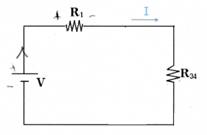
Step 1: The first step is to simplify the circuit. Since $R_3$ and $R_4$ are in parallel, we can replace them with their equivalent resistance: \[ R_{34} = \frac{R_3R_4}{R_3+R_4}. \] The equivalent circuit looks much simpler now, and in particular there is only one current: the current $I$ flowing around the loop.
Step 2: To calculate the value of the current, we divide the value of the voltage source $V$ by the total resistance of the circuit $R_{tot} = R_1 + R_{34}$: \[ I = \frac{V}{R_1+R_{34}} = \frac{V_{tot}}{R_{tot}}. \]
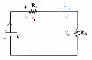
Step 3: Now that we know the current flowing in this loop we can compute the voltages dropped on $R_1$ and $R_{34}$ respectively. To calculate these voltages, we use $V=IR$ again: \[ V_1 = IR_1 = \frac{V}{R_1+R_{34}}R_1, \qquad V_{34} = IR_{34} = \frac{V}{R_1+R_{34}}R_{34}. \]
Step 4: It is time to de-simplify the circuit and replace the equivalent resistance $R_{34}$ with the real circuit which had $R_3$ and $R_4$ in parallel. In doing so, we introduce two new variables $I_3$ and $I_4$, the currents flowing in each branch of the circuit.
Step 4: In this last step we have to find the current $I_4$. This is easy to do since we know the value of the voltage $V_{34}$ across it leads. Indeed we can find both currents $I_3$ and $I_4$ by using the $V=IR$ formula again: \[ I_3 = \frac{V_{34}}{R_3}, \qquad I_4 = \frac{V_{34}}{R_4}. \] Note that the two resistors in parallel have the same voltage across them.
We were able to carry out the entire calculation using variables. This is a good approach to follow, rather than solving with the numerical values of the resistors. Let's say that your teacher wants you to answer the problem for a particular set of parameters: the voltage source has $V=7[V]$ and $R_1=3[\Omega]$, $R_2=356[\Omega]$, $R_3=8[\Omega]$ and $R_4=8[\Omega]$. In that case we would have: \[ R_{34} = 8\|8 = \!\!\frac{8\times 8}{8\ + \ 8} = 4[\Omega],\ \ I = \frac{7}{3+4}=1[A], \ \ V_{34} = IR_{34} = 4[V], \ \ I_4 = \frac{V_{34}}{R_4} = \frac{4}{8} = 0.5[A]. \]
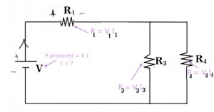
Bonus Step: Since we have all the voltages and currents calculated, let's calculate the power $P=IV$ consumed by the different elements of the circuit.
We first calculate the power consumed by the battery. We have to put a negative current into the equation for power, since the current $I$ is leaving the (+) terminal: \[ P_{\text{batt}} = IV = (-1[A])(7[V])=-7[W]. \] We say that the battery generates 7[W], since negative power consumed, means that this device is actually inputting power into the circuit rather than consuming it.
For the resistors we can use any one of these expressions: $P=IV=IR^2=V^2/R$. \[ P_1 = I^2R_1 = 3[W], \ P_2 = 0, \ P_3 = I_3V_{34} = 0.5[A]4[V]=2[W], \ P_4 = I_4V_{34} = 2[W]. \] Note that we have overall conservation of power in the circuit. The battery produces 7[W] and the resistors consume a total of 7[W].
Electric measurement tools
How do we measure all these things that we have been plugging into equations? Currents, voltages, resistances: how do we see them?
Voltmeter
   ________
  |        |
  | [   V] |
  |        |
  | +    - |
  |_|____|_|
    |    |
    \==  \_==
The voltmeter measures the voltage difference between two points in the circuit. The voltage measured tell us how much electric potential energy the electrons gain (or lose) by going from the point attached to + to the point attached to -.
Observations:
- If you connect the two leads + and - together, then you will measure 0 [V].
There is no potential difference, since you are at the same point.
- Say you have an AA battery. If you connect a voltmeter (+) to the battery (+) and the voltmeter (-) to the battery (-), the voltmeter will report 1.5V. This means that an electric charge gains 1.5V of potential energy when it goes from one terminal to the other.
- If you connect the voltmeter (+) to the battery (-) and vice versa, then it will read -1.5V.
- If you connect 10 AA batteries head to tail, then the voltage between the (+) of the first one and the (-) of the last the voltmeter will measure 15[V].
How does a voltmeter work? It diverts a tiny quantity of electrons from the main circuit and measures the change in their energy as they pass from the (+) side to the (-) side.
Amperemeter
    |
   _|______
  | +      |
  |        |
  | [   A] |
  |        |
  |      - |
  |______|_|
         |
         \____
To measure the current in some wire, you need to open the circuit and connect an ampermeter in series. Thus, the current you are trying to measure will have to pass through the ampermeter and you will be able to measure how big that current is.
Ohmmeter
If you want to measure the resistance, then you use an Ohm-meter.
   ________
  |        |
  | [   Ω] |
  |        |
  |        |
  |_|____|_|
    |    |
    \    \___
     \___
If you put the two leads across a resistor, this device will compute the equivalent resistance $R_{eq}$ for that device. It does this by passing a small current through, and measuring the resulting voltage. The Ohmmetter is essentially the combination of a voltmeter and an ampermeter and it reports the ratio $R_{eq} = V_{\text{resulting}}I_{\text{pushed}}$.
If you want to measure the resistance of a resistor, you have to disconnect it from the rest of the circuit. If you don't do that, the Ohmmeter will report the effective resistance of the whole circuit.
Discussion
We have seen how to solve simple circuits involving resistors. In the next chapter, we will learn how to deal with more complicated arrangements of resistors and in the chapters after that we can learn about the properties of new circuit elements like capacitors or inductors.
