The page you are reading is part of a draft (v2.0) of the "No bullshit guide to math and physics."
The text has since gone through many edits and is now available in print and electronic format. The current edition of the book is v4.0, which is a substantial improvement in terms of content and language (I hired a professional editor) from the draft version.
I'm leaving the old wiki content up for the time being, but I highly engourage you to check out the finished book. You can check out an extended preview here (PDF, 106 pages, 5MB).
Optics
Introduction
A camera consists essentially of two parts: a detector and a lens construction. The detector is some surface that can record the light which hits it. Old-school cameras used the chemical reaction of silver-oxidation under light, whereas modern cameras use electronic photo-detectors.
While the detector is important, that which really makes or brakes a camera is the lens. The lens' job is to take the light reflected off some object (that which you are taking a picture of) and redirect it in an optimal way so that a faithful image forms on the detection surface. The image has to form exactly at the right distance $d_i$ (so that it is in focus) and have exactly the right height $h_i$ (so it fits on the detector).
To understand how lenses transform light, there is just one equation you need to know: \[ \frac{1}{d_o} + \frac{1}{d_i} = \frac{1}{f}, \] where $d_o$ is the distance from the object to the lens, $d_i$ is the distance from the lens to the image and $f$ is called the focal length of the lens. This entire chapter is dedicated to this equation and its applications. It turns out that curved mirrors behave very similarly to lenses, and the same equation can be used to calculate the properties of the images formed by mirrors. Before we talk about curved mirrors and lenses, we will have to learn about the basic properties of light and the laws of reflection and refraction.
Light
Light is pure energy stored in the form of a travelling electromagnetic wave.
The energy of a light particle is stored in the electromagnetic oscillation. During one moment, light is a “pulse” of electric field in space, and during the next instant it is a “pulse” of pure magnetic energy. Think of sending a “wrinkle pulse” down a long rope – where the pulse of mechanical energy is traveling along the rope. Light is like that, but without the rope. Light is just an electro-magnetic pulse and such pulses happen even in empty space. Thus, unlike most other waves you may have seen until now, light does not need a medium to travel in: empty space will do just fine.
The understanding of light as a manifestation of electro-magnetic energy (electromagnetic radiation) is some deep stuff, which is not the subject of this section. We will get to this, after we cover the concept of electric and magnetic fields, electric and magnetic energy and Maxwell's equations. For the moment, when I say “oscillating energy”, I want you to think of a mechanical mass-spring system in which the energy oscillates between the potential energy of the spring and the kinetic energy of the mass. A photon is a similar oscillation between a “magnetic system” part and the “electric system” part, which travels through space at the speed of light.
In this section, we focus on light rays. The vector $\hat{k}$ in the figure describes the direction of travel of the light ray.
  Oh light ray, light ray!
  Where art thou, on this winter day.
Definitions
Light is made up of “light particles” called photons:
- $p$: a photon.
- $E_p$: the Energy of the photon.
- $\lambda$: the wavelength the photon.
- $f$: the frequency of the photon. (Denoted $\nu$ in some texts.)
- $c$: the speed of light in vacuum. $c=2.9979\times 10^{8}$[m/s].
NOINDENT The speed of light depends on the material in which it travels:
- $v_x$: the speed of light in material $x$.
- $n_x$: the diffraction index of material $x$,
which tells you how much slower light is in that material
  relative to the speed of light in vacuum.
  $v_x=c/n_x$.
  Air is pretty much like vacuum,
  so $v_{air} \approx c$ and $n_{air}\approx 1$.
  There are different types of glass used in
  lens-manifacturing with $n$ values ranging from 1.4 to 1.7.
Equations
Like all travelling waves, the propagation speed of light is equal to the product of its frequency times its wavelength. In vacuum we have \[ c = \lambda f. \]
For example, red light of wavelength $\lambda=700$n[m], has frequency $f=428.27$THz since the speed of light is $c=2.9979\times 10^{8}$[m/s].
The energy of a beam of light is proportional to the intensity of the light (how many photon per second are being emitted) and the energy carried by each photon. The energy of a photon is proportional to its frequency: \[ E_p = \hbar f, \] where $\hbar=1.05457\times 10^{-34}$ is Plank's constant. The above equation is a big deal, since it applies not just to light but to all forms of electromagnetic radiation. The higher the frequency, the more energy per photon there is. Einstein got a Nobel prize for figuring out the photoelectric effect which is a manifestation of the above equation.
The speed of light in a material $x$ with refractive index $n_x$ is \[ v_x = \frac{c}{n_x}. \]
Here is a list of refractive indices for some common materials: $n_{vacuum}\equiv 1.00$, $n_{air} = 1.00029$, $n_{ice}=1.31$, $n_{water}=1.33$, $n_{fused\ quartz}=1.46$, $n_{NaCl}=1.54$, Crown glass 1.52-1.62, Flint glass 1.57-1.75, $n_{sapphire}=1.77$, and $n_{diamond}=2.417$.
Discussion
Visible light
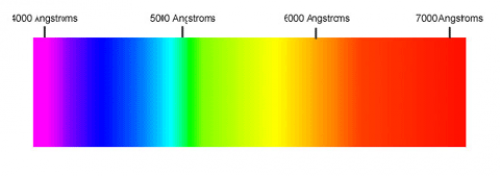
Our eyes are able to distinguish certain wavelengths of light as different colours.
| Color | Wavelength (nm) |
|---|---|
| Red | 780 - 622 |
| Orange | 622 - 597 |
| Yellow | 597 - 577 |
| Green | 577 - 492 |
| Blue | 492 - 455 |
| Violet | 455 - 390 |
Note that units of wavelength are tiny numbers like: nanometers $1[\textrm{nm}]=10^{-9}[\textrm{m}]$ or Armstrongs $1[\textrm{A}]=10^{-10}[\textrm{m}]$.
The electromagnetic spectrum
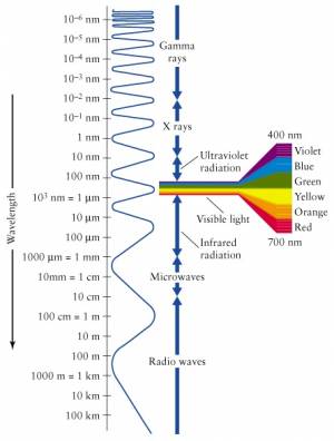 Visible light is only a small part of the electromagnetic spectrum.
Waves with frequency higher than that of violet light are called
ultraviolet (UV) radiation and cannot be seen by the human eye.
Also, frequencies lower than that of red light (infrared)
are not seen, but can sometimes be felt as heat.
The EM spectrum extends to all sorts of frequencies (and therefore wavelengths, by $c=\lambda f$). We have different names for the different parts of the EM spectrum. The highest energy particles (highest frequency $\to$ shortest wavelength) are called gamma rays ($\gamma$-rays). We are constantly bombarded by gamma rays coming from outer space with tremendous energy. These $\gamma$-rays are generated by nuclear reactions inside distance stars.
Particles with less energy than $\gamma$-rays are called X-rays. These are still energetic enough that they easily pass through most parts of your body like a warm knife through butter. Only your bones offer some resistance, which is kind of useful in medical imaging since all bone structure can be seen in contrast when taking an X-ray picture.
The frequencies below the visible range (wavelengths longer than that of visible light) are populated by radio waves. And when I say radio, I don't mean specifically radio, but any form of wireless communication. Starting from 4G (or whatever cell phones have gotten to these days), then the top GSM bands at 2.2-2.4GHz, the low GSM bands 800-900MHz, and then going into TV frequencies, FM frequencies (87–108MHz) and finally AM frequencies (153kHz–26.1MHz). It is all radio. It is all electromagnetic radiation emitted by antennas, travelling through space and being received by other antennas.
Light rays
In this section we will study how light rays get reflected off the surfaces of objects and what happens when light rays reach the boundary between two different materials.
Definitions
The speed of light depends on the material where it travels:
- $v_x$: the speed of light in material $x$.
- $n_x$: the diffraction index of material $x$,
which tells you how much slower light is in that material.
$v_x=c/n_x$.
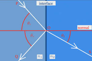
When an incoming ray of light comes to the surface of a transparent object, part of it will be reflected and part of it will be transmitted. We measure all angles with respect to the normal, which is the direction perpendicular to the interface.
- $\theta_{i}$: The incoming or incidence angle.
- $\theta_{r}$: The reflection angle.
- $\theta_{t}$: The transmission angle:
the angle of the light that goes into the object.
Formulas
Reflection
Light that hits a reflective surface will bounce back exactly at the same angle as it came in on: \[ \theta_{i} = \theta_{r}. \]
Refraction
The transmission angle of light when it goes into a material with different refractive index can be calculated from Snell's law: \[ n_i \sin\theta_{i} = n_t \sin \theta_{t}. \]
Total internal refraction
Light coming in from a medium with low refraction index into a medium with high refraction index gets refracted towards the normal. If the light travels in the opposite direction (from high $n$, to low $n$), then it will get deflected away from the normal. In the latter case, an interesting phenomenon called total internal refraction occurs, whereby light rays incident at sufficiently large angles with the normal get trapped inside the material. The angle at which this phenomenon starts to kick in is called the critical angle $\theta_{crit}$.
Consider a light ray inside a material of refractive indeed $n_x$ surrounded by a material with smaller refractive index $n_y$, $n_x > n_y$. To make this more concrete, think of a trans-continental underground optical cable made of glass $n_x=1.7$ surrounded by some plastic with $n_y=1.3$. All light at an angle greater than: \[ \theta_{crit} = \sin^{-1}\left( \frac{n_y}{n_{x}} \underbrace{\sin(90^\circ)}_{=1} \right) = \sin^{-1}\!\left( \frac{n_y}{n_{x}} \right) = \sin^{-1}\!\left( \frac{1.3}{1.7} \right) = 49.88^\circ, \] will get reflected every time it reaches the surface of the optical cable. Thus, if you shine a laser pointer into one end of such a fibre-optical cable in California, 100% of that laser light will come out in Japan. Most high-capacity communication links around the world are based around this amazing property of light. In other words: no total internal refraction means no internet.
Examples
What is wrong in this picture?
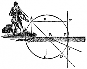
Here is an illustration from one of René Descartes' books, which shows a man in funny pants with some sort of lantern which produces a light ray that goes into the water.
Q: What is wrong with the picture?
Hint: Recall that $n_{air}=1$ and $n_{water}=1.33$, so $n_i < n_t$.
Hint 2: What should happen to the angles of the light ray?
A: Suppose that the line $\overline{AB}$, is at $45^\circ$ angle, then after entering the water at $B$, the ray should be deflected towards the normal, i.e., it should pass somewhere between $G$ and $D$. If you wanted to be precise and calculate the transmission angle then we would use: \[ n_i \sin\theta_{i} = n_t \sin \theta_{t}, \] filled in with the values for air and water \[ 1 \sin(45^\circ) = 1.33 \sin( \theta_{t} ), \] and solved for $\theta_{t}$ (the refracted angle) we would get: \[ \theta_{t} = \sin^{-1}\left( \frac{\sqrt{2}}{2\times1.33} \right) = 32.1^\circ. \] The mistake apparently is due to Descartes' printer who got confused and measured angles with respect to the surface of the water. Don't make that mistake: remember to always measure angles with respect to the normal. The correct drawing should have the light ray going at an angle of $32.1^\circ$ with respect to the line $\overline{BG}$.
Explanations
Refraction
To understand refraction you need to imagine “wave fronts” perpendicular to the light rays. Because light comes in at an angle, one part of the wave front will be in material $n_i$ and the other will be in material $n_t$. Suppose $n_i < n_t$, then the part of the wavefront in the $n_t$ material will move slower so angles of the wavefronts will change. The precise relationship between the angles will depend on the refractive indices of the two materials:
\[ n_i \sin\theta_{i} = n_t \sin \theta_{t}. \]
Total internal refraction
Whenever $n_i > n_t$, we reach a certain point where the formula: \[ n_i \sin\theta_{i} = n_t \sin \theta_{t}, \] brakes down. If the transmitted angle $\theta_t$ becomes greater than $90^\circ$ (the critical transmission angle) it will not be transmitted at all. Instead, 100% of the light ray will get reflected back into the material.
To find the critical incident angle solve for $\theta_i$ in: \[ n_i \sin\theta_{i} = n_t \sin 90^\circ, \] \[ \theta_{crit} = \sin^{-1}\left( \frac{n_t}{n_{i}} \right). \]
The summary of the “what happens when a light ray comes to a boundary”-story is as follows:
- If $-\theta_{crit} < \theta_i < \theta_{crit}$, then some part of the light will be
transmitted at an angle $\theta_t$ and some part will be reflected at an angle $\theta_r=\theta_i$.
- If $\theta_i \geq \theta_{crit}$, then all the light will get reflected at an angle $\theta_r=\theta_i$.
Note that when going from a low $n$ medium into a high $n$ medium, there is no critical angle – there will always be some part of the light that is transmitted.
Parabolic shapes
The parabolic curve has a special importance in optics. Consider for example a very weak radio signal coming from a satellite in orbit. If you use just a regular radio receiver, the signal will be so weak as to be indistinguishable from the background noise. However, if you use a parabolic satellite dish to collect the power from a large surface area and focus it on the receiver, then you will be able to detect the signal. This works because of the parabolic shape of the satellite dish: all radio wave coming in from far away will get reflected towards the same point—the focal point of the parabola. Thus, if you put your receiver at the focal point, it will have the signal power from the whole dish redirected right to it.
Depending on the shape of the parabola (which way it curves and how strong the curvature is) the focal point or focus will be at a different place. In the next two sections, we will study parabolic mirrors and lenses. We will use the “horizontal rays get reflected towards the focus”-fact to draw optics diagrams and calculate where images will be formed.
Mirrors
Definitions
To understand how curved mirrors work, we imagine some test object (usually drawn as an arrow, or a candle) and the test image it forms.
- $d_o$: The distance of the object from the mirror.
- $d_i$: The distance of the image from the mirror.
- $f$: The focal length of the mirror.
- $h_o$: The height of the object.
- $h_i$: The height of the image.
- $M$: The magnification $M=h_i/h_o$.
When drawing optics diagrams with mirrors, we can draw the following three rays:
- $R_\alpha$: A horizontal incoming ray which gets redirected towards
the focus after it hits the mirror.
- $R_\beta$: A ray that passes through the focus and gets redirected horizontally
after it hits the mirror.
- $R_\gamma$: A ray that hits the mirror right in the centre and bounces back
at the same angle at which it came in.
Formulas
The following formula can be used to calculate where an image will be formed, given that you know the focal length of the mirror and the distance $d_o$ of the object: \[ \frac{1}{d_o} + \frac{1}{d_i} = \frac{1}{f}. \]
We follow the convention that distances measured from the reflective side of the mirror are positive, and distances behind the mirror are negative.
The magnification is defined as: \[ M = \frac{h_i}{h_o} = \frac{|d_i|}{|d_o|} \] How much bigger is the image compared to the object?
Though it might sound confusing, we will talk about magnification even when the image is smaller than the object; in those cases we say we have fractional magnification.
Examples
Visual examples
Mirrors reflect light, so it is usual to see an image formed on the same side as where it came from. This leads to the following convention:
- If the image forms on the usual side (in front of the mirror),
then we say it has positive distance $d_i$.
- If the image forms behind the mirror, then it has negative $d_i$.
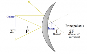
Let us first look at the kind of mirror that you see in metro tunnels: convex mirror. These mirrors will give you a very broad view, and if someone is coming around the corner the hope is that your peripheral vision will be able to spot them in the mirror and you won't bump into each other.
I am going to draw $R_\alpha$ and $R_\gamma$:
Note that the image is “virtual”, since it appears to form inside the mirror.
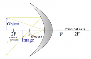
Here is a drawing of a concave mirror instead, with the rays $R_\alpha$ and $R_\gamma$ drawn again.
Can you add the ray $R_\beta$ (through the focus)? As you can see, any two rays out of the three are sufficient to figure out where the image will be: just find the point where the rays meet.
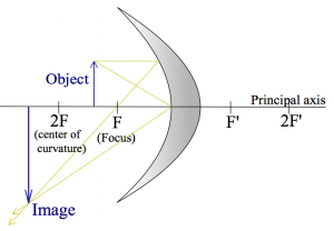
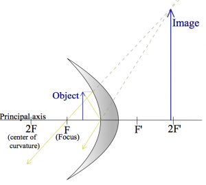
Here are two more examples where the object its placed closer and closer to the mirror.
These are meant to illustrate that the same curved surface, and the same object can lead to very different images depending on where the object is placed relative to the focal point.
Numerical example 1
OK, let's do an exercise of the “can you draw straight lines using a ruler” type now. You will need a piece of white paper, a ruler and a pencil. Go get this stuff, I will be waiting right here.
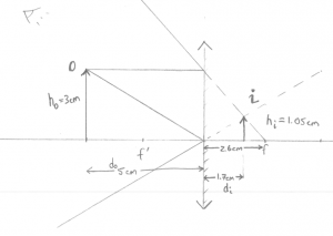
Q: A convex mirror (like in the metro) is placed at the origin. An object of height 3[cm] is placed $x=5$[cm] away from the mirror. Where will the image be formed?
Geometric answer: Instead of trying to draw a curved mirror, we will draw a straight line. This is called the thin lens approximation (in this case, thin mirror) and it will make the drawing of lines much simpler. Take out the ruler and draw the two rays $R_\alpha$ and $R_\gamma$ as I did:
Then I can use the ruler to measure out $d_i\approx 1.7cm$.
Formula Answer: Using the formula \[ \frac{1}{d_o} + \frac{1}{d_i} = \frac{1}{f}, \] with the appropriate values filled in \[ \frac{1}{5} + \frac{1}{d_i} = \frac{1}{-2.6}, \] or \[ d_i = 1.0/(-1.0/2.6 - 1.0/5) = -1.71 \text{[cm]}. \] Nice.
Observe that (1) I used a negative focal point for the mirror since in some sense the focal point is “behind” the mirror, and (2) the image is formed behind the mirror, which means that it is virtual: this is where the arrow will appear to an the observing eye drawn in the top left corner.
Numerical example 2
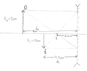
Now we have a concave mirror with focal length $f=2.6cm$ and we measure the distances the same way (positive to the left).
Q: An object is placed at $d_0=7$[cm] from the mirror. Where will the image form? What is the height of the image?
Geometric answer: Taking out the ruler, you can choose to draw any of the three rays. I picked $R_\alpha$ and $R_\beta$ since they are the easiest to draw:
Then measuring with the ruler I find that $d_i \approx 4.3$[cm], and that the image is height $h_i\approx-1.9$[cm], where negative height means that the image is upside down.
Formula Answer: With the formula now. We start from \[ \frac{1}{d_o} + \frac{1}{d_i} = \frac{1}{f}, \] and fill in what we know \[ \frac{1}{7} + \frac{1}{d_i} = \frac{1}{2.6}, \] then solve for $d_i$: \[ d_i = 1.0/(1.0/2.6 - 1.0/7.0) = 4.136 \text{[cm]}. \] To find the height of the image we use \[ \frac{h_i}{h_o} = \frac{d_i}{d_o}, \] so \[ h_i = 3 \times \frac{4.136}{7.0} = 3 \times 4.13/7.0 = 1.77 \text{[cm]}. \] You still need the drawing to figure out that the image is inverted though.
Generally, I would trust the numeric answers from the formula more, but read the signs of the answers from the drawing. Distances in front of the mirror are positive whereas images formed behind the mirror have negative distance.
Links
Lenses
Definitions
To understand how lenses work, we imagine again some test object. (an arrow) and the test image it forms.
- $d_o$: The distance of the object from the lens.
- $d_i$: The distance of the image from the lens.
- $f$: The focal length of the lens.
- $h_o$: The height of the object.
- $h_i$: The height of the image.
- $M$: The magnification $M=h_i/h_o$.
When drawing lens diagrams, we use the following representative rays:
- $R_\alpha$: A horizontal incoming ray which gets redirected towards
the focus after it passes through the lens.
- $R_\beta$: A ray that passes through the focus and gets redirected horizontally
after the lens.
- $R_\gamma$: A ray that passes exactly through the centre of the lens
and travels in a straight line.
Formulas
\[ \frac{1}{d_o} + \frac{1}{d_i} = \frac{1}{f} \]
\[ M = \frac{h_i}{h_o} = \frac{|d_i|}{|d_o|} \]
Examples
Visual
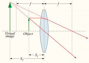
Fist consider the typical magnifying glass situation. You put the object close to the lens, and looking from the side, the object will appear magnified.
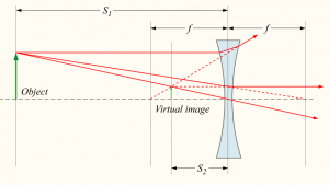
A similar setup with a diverging lens. This time the image will appear to the observer to be smaller than the object.
Note that in the above two examples, if you used the formula you would get a negative $d_i$ value since the image is not formed on the “right” side. We say the image is virtual.
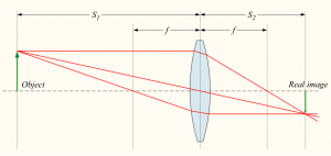
Now for an example where a real image is formed:
In this example all the quantities $f$, $d_o$ and $d_i$ are positive.
Numerical
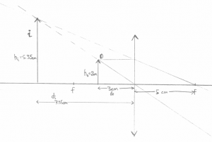
An object is placed at a distance of 3[cm] from a magnifying glass of focal length 5[cm]. Where will the object appear to be?
You should really try this on your own. Just reading about light rays is kind of useless. Try drawing the above by yourself with the ruler. Draw the three kinds of rays: $R_\alpha$, $R_\beta$, and $R_\gamma$.
Here is my drawing.
Numerically we get \[ \frac{1}{d_o} + \frac{1}{d_i} = \frac{1}{f}, \] \[ \frac{1}{3.0} + \frac{1}{d_i} = \frac{1}{5.0}, \] \[ d_i = 1.0/(1.0/5.0 - 1.0/3.0) = -7.50 \text{[cm]}. \]
As you can see, drawings are not very accurate. Always trust the formula for the numeric answers to $d_o$, $d_i$ type of questions.
Multiple lenses
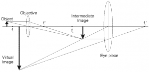
Imagine that the “output” image formed by the first lens is the “input” image to a second lens.
It may look complicated, but if you solve the problem in two steps (1) how the object forms an intermediary image, and (2) how the intermediary image forms the final image you will get things right.
You can also trace all the rays as they pass through the double-lens apparatus:
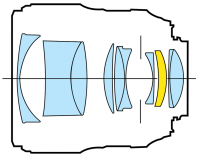 We started this chapter talking about real cameras, so I want to
finish on that note too. To form a clear image, with variable focus and
possibly zoom functionality, we have to use a whole series of lenses,
not just one or two.
For each lens though, we can use the formula and calculate the effects of that lens on the light coming in.
Note that the real world is significantly more complicated than the simple ray picture which we have been using until now. For one, each frequency of light will have a slightly different refraction angle, and sometimes the lens shapes will not be perfect parabolas, so the light rays will not be perfectly redirected towards the focal point.
Discussion
Fresnel lens
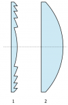 Thicker lenses are stronger. The reason is that the curvature
of a thick lens is bigger and thus light will be refracted more
when it hits the surface.
The actual thickness of the lens is of no importance.
The way rays get deflected by lenses only depends on the angles of
incidence. Indeed, we can cut out all the middle part
of the lens and leave a highly curved surface parts.
This is called a Fresnel lens and it is used in car headlights.
