The page you are reading is part of a draft (v2.0) of the "No bullshit guide to math and physics."
The text has since gone through many edits and is now available in print and electronic format. The current edition of the book is v4.0, which is a substantial improvement in terms of content and language (I hired a professional editor) from the draft version.
I'm leaving the old wiki content up for the time being, but I highly engourage you to check out the finished book. You can check out an extended preview here (PDF, 106 pages, 5MB).
<texit info> author=Ivan Savov title=Electrostatics and an intorudction to magnetism backgroundtext=off </texit>
Front matter
About
This book contains short lessons on topics in math and physics. The coverage of each topic is at the depth required for a university-level course written in a style that is short and to the point. A motivated reader can easily learn enough calculus and mechanics from this book to get an A on the final exam on these subjects. You can learn everything you need to know in two weeks, then you will need another week to practice exercises. Three weeks and you are done.
Calculus and mechanics can be difficult subjects, but they become easy when you break down the concepts into manageable chunks. The most important thing is to learn about the connections between concepts and to understand what is going on intuitively. Every time you learn about some new concept, you need to connect it with all your previous knowledge.
Speaking of previous knowledge...
In order to get off on the right foot, the book begins with a comprehensive review of math fundamentals like algebra, equation solving and functions. Anyone can pick up this book and become proficient in calculus and mechanics regardless of their mathematical background. You can skip the first chapter if you feel comfortable with high school math concepts, though it might still be a good idea for you to do a flyover for review purposes.
Why?
The genesis of this book dates back to my days as an undergraduate student when I was forced to purchase expensive textbooks that were required for my courses. Not only are these textbooks expensive, but they are also long and tedious to read. The standard introductory physics textbook is 1040 pages long and the calculus book is another 1311 pages. I can tell you for a fact that you don't need to read 2300 pages to learn math and physics and calculus, so what is the deal? The reason why mainstream textbooks are so big is that this allows the textbook publishers to suck more money out of you. You wouldn't pay 150 dollars for a 300 page textbook now would you? The fact that a new edition of the textbook comes out every couple of years with almost no changes to the content shows that textbook publishers are not really out to teach you stuff, but only after your money.
Looking at this situation, I said to myself “Something must be done!” and I sat down to write a modern textbook that explains things clearly and concisely. The book you have in your hands.
How?
Each section in this book is like a self-contained private tutorial. Indeed, the lessons you will read grew from my experience as a private tutor. The writing is chill and conversational, but we keep a quick pace through the material. Prerequisites topics are introduced as needed. There are a lot of hands-on explanations through solved examples. We cover the same material as the 400 page textbook in just 40 pages. I call this process information distillation.
Who?
Since this is an “about” section, I will say something about me.
I have been tutoring math and physics privately for more than ten years.
I did my undergraduate studies at McGill University in Electrical Engineering,
then I did a M.Sc. in Physics and I recently completed a Ph.D. in Computer Science.
I have been developing this book in parallel with my studies and,
on the day of my graduation, I founded the Minireference Publishing Co.
revolutionize the textbook industry.
This is the deal. You give me 250 pages of your attention, and I will teach you everything I know about functions, limits, derivatives, integrals, vectors, forces and accelerations. The book which you hold in your hands is the only book you need for the first year of undergraduate studies in science.
Optics
Introduction
A camera consists essentially of two parts: a detector and a lens construction. The detector is some surface that can record the light which hits it. Old-school cameras used the chemical reaction of silver-oxidation under light, whereas modern cameras use electronic photo-detectors.
While the detector is important, that which really makes or brakes a camera is the lens. The lens' job is to take the light reflected off some object (that which you are taking a picture of) and redirect it in an optimal way so that a faithful image forms on the detection surface. The image has to form exactly at the right distance $d_i$ (so that it is in focus) and have exactly the right height $h_i$ (so it fits on the detector).
To understand how lenses transform light, there is just one equation you need to know: \[ \frac{1}{d_o} + \frac{1}{d_i} = \frac{1}{f}, \] where $d_o$ is the distance from the object to the lens, $d_i$ is the distance from the lens to the image and $f$ is called the focal length of the lens. This entire chapter is dedicated to this equation and its applications. It turns out that curved mirrors behave very similarly to lenses, and the same equation can be used to calculate the properties of the images formed by mirrors. Before we talk about curved mirrors and lenses, we will have to learn about the basic properties of light and the laws of reflection and refraction.
Light
Light is pure energy stored in the form of a travelling electromagnetic wave.
The energy of a light particle is stored in the electromagnetic oscillation. During one moment, light is a “pulse” of electric field in space, and during the next instant it is a “pulse” of pure magnetic energy. Think of sending a “wrinkle pulse” down a long rope – where the pulse of mechanical energy is traveling along the rope. Light is like that, but without the rope. Light is just an electro-magnetic pulse and such pulses happen even in empty space. Thus, unlike most other waves you may have seen until now, light does not need a medium to travel in: empty space will do just fine.
The understanding of light as a manifestation of electro-magnetic energy (electromagnetic radiation) is some deep stuff, which is not the subject of this section. We will get to this, after we cover the concept of electric and magnetic fields, electric and magnetic energy and Maxwell's equations. For the moment, when I say “oscillating energy”, I want you to think of a mechanical mass-spring system in which the energy oscillates between the potential energy of the spring and the kinetic energy of the mass. A photon is a similar oscillation between a “magnetic system” part and the “electric system” part, which travels through space at the speed of light.
In this section, we focus on light rays. The vector $\hat{k}$ in the figure describes the direction of travel of the light ray.
  Oh light ray, light ray!
  Where art thou, on this winter day.
Definitions
Light is made up of “light particles” called photons:
- $p$: a photon.
- $E_p$: the Energy of the photon.
- $\lambda$: the wavelength the photon.
- $f$: the frequency of the photon. (Denoted $\nu$ in some texts.)
- $c$: the speed of light in vacuum. $c=2.9979\times 10^{8}$[m/s].
NOINDENT The speed of light depends on the material in which it travels:
- $v_x$: the speed of light in material $x$.
- $n_x$: the diffraction index of material $x$,
which tells you how much slower light is in that material
  relative to the speed of light in vacuum.
  $v_x=c/n_x$.
  Air is pretty much like vacuum,
  so $v_{air} \approx c$ and $n_{air}\approx 1$.
  There are different types of glass used in
  lens-manifacturing with $n$ values ranging from 1.4 to 1.7.
Equations
Like all travelling waves, the propagation speed of light is equal to the product of its frequency times its wavelength. In vacuum we have \[ c = \lambda f. \]
For example, red light of wavelength $\lambda=700$n[m], has frequency $f=428.27$THz since the speed of light is $c=2.9979\times 10^{8}$[m/s].
The energy of a beam of light is proportional to the intensity of the light (how many photon per second are being emitted) and the energy carried by each photon. The energy of a photon is proportional to its frequency: \[ E_p = \hbar f, \] where $\hbar=1.05457\times 10^{-34}$ is Plank's constant. The above equation is a big deal, since it applies not just to light but to all forms of electromagnetic radiation. The higher the frequency, the more energy per photon there is. Einstein got a Nobel prize for figuring out the photoelectric effect which is a manifestation of the above equation.
The speed of light in a material $x$ with refractive index $n_x$ is \[ v_x = \frac{c}{n_x}. \]
Here is a list of refractive indices for some common materials: $n_{vacuum}\equiv 1.00$, $n_{air} = 1.00029$, $n_{ice}=1.31$, $n_{water}=1.33$, $n_{fused\ quartz}=1.46$, $n_{NaCl}=1.54$, Crown glass 1.52-1.62, Flint glass 1.57-1.75, $n_{sapphire}=1.77$, and $n_{diamond}=2.417$.
Discussion
Visible light
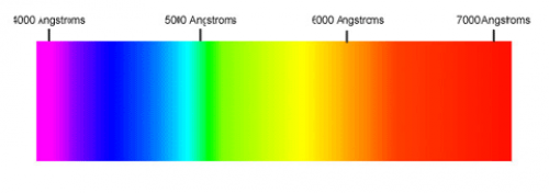
Our eyes are able to distinguish certain wavelengths of light as different colours.
| Color | Wavelength (nm) |
|---|---|
| Red | 780 - 622 |
| Orange | 622 - 597 |
| Yellow | 597 - 577 |
| Green | 577 - 492 |
| Blue | 492 - 455 |
| Violet | 455 - 390 |
Note that units of wavelength are tiny numbers like: nanometers $1[\textrm{nm}]=10^{-9}[\textrm{m}]$ or Armstrongs $1[\textrm{A}]=10^{-10}[\textrm{m}]$.
The electromagnetic spectrum
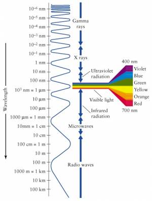 Visible light is only a small part of the electromagnetic spectrum.
Waves with frequency higher than that of violet light are called
ultraviolet (UV) radiation and cannot be seen by the human eye.
Also, frequencies lower than that of red light (infrared)
are not seen, but can sometimes be felt as heat.
The EM spectrum extends to all sorts of frequencies (and therefore wavelengths, by $c=\lambda f$). We have different names for the different parts of the EM spectrum. The highest energy particles (highest frequency $\to$ shortest wavelength) are called gamma rays ($\gamma$-rays). We are constantly bombarded by gamma rays coming from outer space with tremendous energy. These $\gamma$-rays are generated by nuclear reactions inside distance stars.
Particles with less energy than $\gamma$-rays are called X-rays. These are still energetic enough that they easily pass through most parts of your body like a warm knife through butter. Only your bones offer some resistance, which is kind of useful in medical imaging since all bone structure can be seen in contrast when taking an X-ray picture.
The frequencies below the visible range (wavelengths longer than that of visible light) are populated by radio waves. And when I say radio, I don't mean specifically radio, but any form of wireless communication. Starting from 4G (or whatever cell phones have gotten to these days), then the top GSM bands at 2.2-2.4GHz, the low GSM bands 800-900MHz, and then going into TV frequencies, FM frequencies (87–108MHz) and finally AM frequencies (153kHz–26.1MHz). It is all radio. It is all electromagnetic radiation emitted by antennas, travelling through space and being received by other antennas.
Light rays
In this section we will study how light rays get reflected off the surfaces of objects and what happens when light rays reach the boundary between two different materials.
Definitions
The speed of light depends on the material where it travels:
- $v_x$: the speed of light in material $x$.
- $n_x$: the diffraction index of material $x$,
which tells you how much slower light is in that material.
$v_x=c/n_x$.
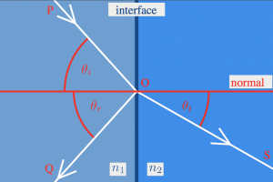
When an incoming ray of light comes to the surface of a transparent object, part of it will be reflected and part of it will be transmitted. We measure all angles with respect to the normal, which is the direction perpendicular to the interface.
- $\theta_{i}$: The incoming or incidence angle.
- $\theta_{r}$: The reflection angle.
- $\theta_{t}$: The transmission angle:
the angle of the light that goes into the object.
Formulas
Reflection
Light that hits a reflective surface will bounce back exactly at the same angle as it came in on: \[ \theta_{i} = \theta_{r}. \]
Refraction
The transmission angle of light when it goes into a material with different refractive index can be calculated from Snell's law: \[ n_i \sin\theta_{i} = n_t \sin \theta_{t}. \]
Total internal refraction
Light coming in from a medium with low refraction index into a medium with high refraction index gets refracted towards the normal. If the light travels in the opposite direction (from high $n$, to low $n$), then it will get deflected away from the normal. In the latter case, an interesting phenomenon called total internal refraction occurs, whereby light rays incident at sufficiently large angles with the normal get trapped inside the material. The angle at which this phenomenon starts to kick in is called the critical angle $\theta_{crit}$.
Consider a light ray inside a material of refractive indeed $n_x$ surrounded by a material with smaller refractive index $n_y$, $n_x > n_y$. To make this more concrete, think of a trans-continental underground optical cable made of glass $n_x=1.7$ surrounded by some plastic with $n_y=1.3$. All light at an angle greater than: \[ \theta_{crit} = \sin^{-1}\left( \frac{n_y}{n_{x}} \underbrace{\sin(90^\circ)}_{=1} \right) = \sin^{-1}\!\left( \frac{n_y}{n_{x}} \right) = \sin^{-1}\!\left( \frac{1.3}{1.7} \right) = 49.88^\circ, \] will get reflected every time it reaches the surface of the optical cable. Thus, if you shine a laser pointer into one end of such a fibre-optical cable in California, 100% of that laser light will come out in Japan. Most high-capacity communication links around the world are based around this amazing property of light. In other words: no total internal refraction means no internet.
Examples
What is wrong in this picture?
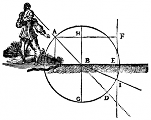
Here is an illustration from one of René Descartes' books, which shows a man in funny pants with some sort of lantern which produces a light ray that goes into the water.
Q: What is wrong with the picture?
Hint: Recall that $n_{air}=1$ and $n_{water}=1.33$, so $n_i < n_t$.
Hint 2: What should happen to the angles of the light ray?
A: Suppose that the line $\overline{AB}$, is at $45^\circ$ angle, then after entering the water at $B$, the ray should be deflected towards the normal, i.e., it should pass somewhere between $G$ and $D$. If you wanted to be precise and calculate the transmission angle then we would use: \[ n_i \sin\theta_{i} = n_t \sin \theta_{t}, \] filled in with the values for air and water \[ 1 \sin(45^\circ) = 1.33 \sin( \theta_{t} ), \] and solved for $\theta_{t}$ (the refracted angle) we would get: \[ \theta_{t} = \sin^{-1}\left( \frac{\sqrt{2}}{2\times1.33} \right) = 32.1^\circ. \] The mistake apparently is due to Descartes' printer who got confused and measured angles with respect to the surface of the water. Don't make that mistake: remember to always measure angles with respect to the normal. The correct drawing should have the light ray going at an angle of $32.1^\circ$ with respect to the line $\overline{BG}$.
Explanations
Refraction
To understand refraction you need to imagine “wave fronts” perpendicular to the light rays. Because light comes in at an angle, one part of the wave front will be in material $n_i$ and the other will be in material $n_t$. Suppose $n_i < n_t$, then the part of the wavefront in the $n_t$ material will move slower so angles of the wavefronts will change. The precise relationship between the angles will depend on the refractive indices of the two materials:
\[ n_i \sin\theta_{i} = n_t \sin \theta_{t}. \]
Total internal refraction
Whenever $n_i > n_t$, we reach a certain point where the formula: \[ n_i \sin\theta_{i} = n_t \sin \theta_{t}, \] brakes down. If the transmitted angle $\theta_t$ becomes greater than $90^\circ$ (the critical transmission angle) it will not be transmitted at all. Instead, 100% of the light ray will get reflected back into the material.
To find the critical incident angle solve for $\theta_i$ in: \[ n_i \sin\theta_{i} = n_t \sin 90^\circ, \] \[ \theta_{crit} = \sin^{-1}\left( \frac{n_t}{n_{i}} \right). \]
The summary of the “what happens when a light ray comes to a boundary”-story is as follows:
- If $-\theta_{crit} < \theta_i < \theta_{crit}$, then some part of the light will be
transmitted at an angle $\theta_t$ and some part will be reflected at an angle $\theta_r=\theta_i$.
- If $\theta_i \geq \theta_{crit}$, then all the light will get reflected at an angle $\theta_r=\theta_i$.
Note that when going from a low $n$ medium into a high $n$ medium, there is no critical angle – there will always be some part of the light that is transmitted.
Parabolic shapes
The parabolic curve has a special importance in optics. Consider for example a very weak radio signal coming from a satellite in orbit. If you use just a regular radio receiver, the signal will be so weak as to be indistinguishable from the background noise. However, if you use a parabolic satellite dish to collect the power from a large surface area and focus it on the receiver, then you will be able to detect the signal. This works because of the parabolic shape of the satellite dish: all radio wave coming in from far away will get reflected towards the same point—the focal point of the parabola. Thus, if you put your receiver at the focal point, it will have the signal power from the whole dish redirected right to it.
Depending on the shape of the parabola (which way it curves and how strong the curvature is) the focal point or focus will be at a different place. In the next two sections, we will study parabolic mirrors and lenses. We will use the “horizontal rays get reflected towards the focus”-fact to draw optics diagrams and calculate where images will be formed.
Mirrors
Definitions
To understand how curved mirrors work, we imagine some test object (usually drawn as an arrow, or a candle) and the test image it forms.
- $d_o$: The distance of the object from the mirror.
- $d_i$: The distance of the image from the mirror.
- $f$: The focal length of the mirror.
- $h_o$: The height of the object.
- $h_i$: The height of the image.
- $M$: The magnification $M=h_i/h_o$.
When drawing optics diagrams with mirrors, we can draw the following three rays:
- $R_\alpha$: A horizontal incoming ray which gets redirected towards
the focus after it hits the mirror.
- $R_\beta$: A ray that passes through the focus and gets redirected horizontally
after it hits the mirror.
- $R_\gamma$: A ray that hits the mirror right in the centre and bounces back
at the same angle at which it came in.
Formulas
The following formula can be used to calculate where an image will be formed, given that you know the focal length of the mirror and the distance $d_o$ of the object: \[ \frac{1}{d_o} + \frac{1}{d_i} = \frac{1}{f}. \]
We follow the convention that distances measured from the reflective side of the mirror are positive, and distances behind the mirror are negative.
The magnification is defined as: \[ M = \frac{h_i}{h_o} = \frac{|d_i|}{|d_o|} \] How much bigger is the image compared to the object?
Though it might sound confusing, we will talk about magnification even when the image is smaller than the object; in those cases we say we have fractional magnification.
Examples
Visual examples
Mirrors reflect light, so it is usual to see an image formed on the same side as where it came from. This leads to the following convention:
- If the image forms on the usual side (in front of the mirror),
then we say it has positive distance $d_i$.
- If the image forms behind the mirror, then it has negative $d_i$.
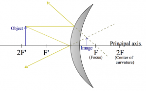
Let us first look at the kind of mirror that you see in metro tunnels: convex mirror. These mirrors will give you a very broad view, and if someone is coming around the corner the hope is that your peripheral vision will be able to spot them in the mirror and you won't bump into each other.
I am going to draw $R_\alpha$ and $R_\gamma$:
Note that the image is “virtual”, since it appears to form inside the mirror.
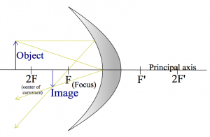
Here is a drawing of a concave mirror instead, with the rays $R_\alpha$ and $R_\gamma$ drawn again.
Can you add the ray $R_\beta$ (through the focus)? As you can see, any two rays out of the three are sufficient to figure out where the image will be: just find the point where the rays meet.
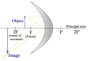
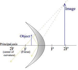
Here are two more examples where the object its placed closer and closer to the mirror.
These are meant to illustrate that the same curved surface, and the same object can lead to very different images depending on where the object is placed relative to the focal point.
Numerical example 1
OK, let's do an exercise of the “can you draw straight lines using a ruler” type now. You will need a piece of white paper, a ruler and a pencil. Go get this stuff, I will be waiting right here.
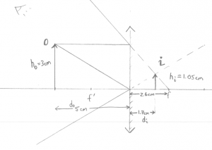
Q: A convex mirror (like in the metro) is placed at the origin. An object of height 3[cm] is placed $x=5$[cm] away from the mirror. Where will the image be formed?
Geometric answer: Instead of trying to draw a curved mirror, we will draw a straight line. This is called the thin lens approximation (in this case, thin mirror) and it will make the drawing of lines much simpler. Take out the ruler and draw the two rays $R_\alpha$ and $R_\gamma$ as I did:
Then I can use the ruler to measure out $d_i\approx 1.7cm$.
Formula Answer: Using the formula \[ \frac{1}{d_o} + \frac{1}{d_i} = \frac{1}{f}, \] with the appropriate values filled in \[ \frac{1}{5} + \frac{1}{d_i} = \frac{1}{-2.6}, \] or \[ d_i = 1.0/(-1.0/2.6 - 1.0/5) = -1.71 \text{[cm]}. \] Nice.
Observe that (1) I used a negative focal point for the mirror since in some sense the focal point is “behind” the mirror, and (2) the image is formed behind the mirror, which means that it is virtual: this is where the arrow will appear to an the observing eye drawn in the top left corner.
Numerical example 2
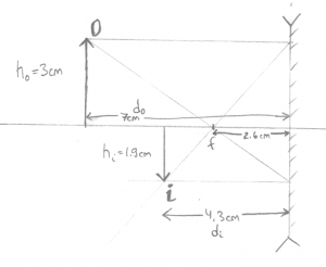
Now we have a concave mirror with focal length $f=2.6cm$ and we measure the distances the same way (positive to the left).
Q: An object is placed at $d_0=7$[cm] from the mirror. Where will the image form? What is the height of the image?
Geometric answer: Taking out the ruler, you can choose to draw any of the three rays. I picked $R_\alpha$ and $R_\beta$ since they are the easiest to draw:
Then measuring with the ruler I find that $d_i \approx 4.3$[cm], and that the image is height $h_i\approx-1.9$[cm], where negative height means that the image is upside down.
Formula Answer: With the formula now. We start from \[ \frac{1}{d_o} + \frac{1}{d_i} = \frac{1}{f}, \] and fill in what we know \[ \frac{1}{7} + \frac{1}{d_i} = \frac{1}{2.6}, \] then solve for $d_i$: \[ d_i = 1.0/(1.0/2.6 - 1.0/7.0) = 4.136 \text{[cm]}. \] To find the height of the image we use \[ \frac{h_i}{h_o} = \frac{d_i}{d_o}, \] so \[ h_i = 3 \times \frac{4.136}{7.0} = 3 \times 4.13/7.0 = 1.77 \text{[cm]}. \] You still need the drawing to figure out that the image is inverted though.
Generally, I would trust the numeric answers from the formula more, but read the signs of the answers from the drawing. Distances in front of the mirror are positive whereas images formed behind the mirror have negative distance.
Links
Lenses
Definitions
To understand how lenses work, we imagine again some test object. (an arrow) and the test image it forms.
- $d_o$: The distance of the object from the lens.
- $d_i$: The distance of the image from the lens.
- $f$: The focal length of the lens.
- $h_o$: The height of the object.
- $h_i$: The height of the image.
- $M$: The magnification $M=h_i/h_o$.
When drawing lens diagrams, we use the following representative rays:
- $R_\alpha$: A horizontal incoming ray which gets redirected towards
the focus after it passes through the lens.
- $R_\beta$: A ray that passes through the focus and gets redirected horizontally
after the lens.
- $R_\gamma$: A ray that passes exactly through the centre of the lens
and travels in a straight line.
Formulas
\[ \frac{1}{d_o} + \frac{1}{d_i} = \frac{1}{f} \]
\[ M = \frac{h_i}{h_o} = \frac{|d_i|}{|d_o|} \]
Examples
Visual
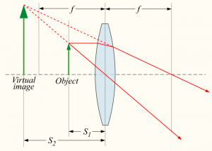
Fist consider the typical magnifying glass situation. You put the object close to the lens, and looking from the side, the object will appear magnified.
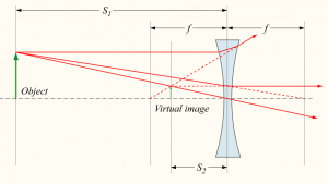
A similar setup with a diverging lens. This time the image will appear to the observer to be smaller than the object.
Note that in the above two examples, if you used the formula you would get a negative $d_i$ value since the image is not formed on the “right” side. We say the image is virtual.
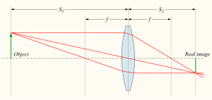
Now for an example where a real image is formed:
In this example all the quantities $f$, $d_o$ and $d_i$ are positive.
Numerical
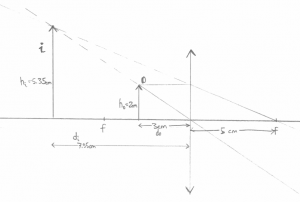
An object is placed at a distance of 3[cm] from a magnifying glass of focal length 5[cm]. Where will the object appear to be?
You should really try this on your own. Just reading about light rays is kind of useless. Try drawing the above by yourself with the ruler. Draw the three kinds of rays: $R_\alpha$, $R_\beta$, and $R_\gamma$.
Here is my drawing.
Numerically we get \[ \frac{1}{d_o} + \frac{1}{d_i} = \frac{1}{f}, \] \[ \frac{1}{3.0} + \frac{1}{d_i} = \frac{1}{5.0}, \] \[ d_i = 1.0/(1.0/5.0 - 1.0/3.0) = -7.50 \text{[cm]}. \]
As you can see, drawings are not very accurate. Always trust the formula for the numeric answers to $d_o$, $d_i$ type of questions.
Multiple lenses
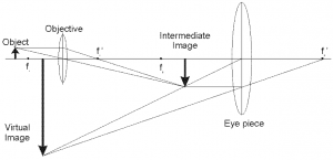
Imagine that the “output” image formed by the first lens is the “input” image to a second lens.
It may look complicated, but if you solve the problem in two steps (1) how the object forms an intermediary image, and (2) how the intermediary image forms the final image you will get things right.
You can also trace all the rays as they pass through the double-lens apparatus:
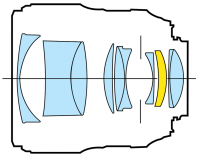 We started this chapter talking about real cameras, so I want to
finish on that note too. To form a clear image, with variable focus and
possibly zoom functionality, we have to use a whole series of lenses,
not just one or two.
For each lens though, we can use the formula and calculate the effects of that lens on the light coming in.
Note that the real world is significantly more complicated than the simple ray picture which we have been using until now. For one, each frequency of light will have a slightly different refraction angle, and sometimes the lens shapes will not be perfect parabolas, so the light rays will not be perfectly redirected towards the focal point.
Discussion
Fresnel lens
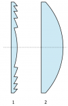 Thicker lenses are stronger. The reason is that the curvature
of a thick lens is bigger and thus light will be refracted more
when it hits the surface.
The actual thickness of the lens is of no importance.
The way rays get deflected by lenses only depends on the angles of
incidence. Indeed, we can cut out all the middle part
of the lens and leave a highly curved surface parts.
This is called a Fresnel lens and it is used in car headlights.
Electricity and Magnetism
Electricity & magnetism
This course is about all things electrical and magnetic. Every object which has a mass $m$ will be affected by gravity. Similarly, every object which has a charge $q$ will feel the electric force $\vec{F}_e$. Furthermore, if a charge is moving then it will also be affected by the magnetic force $\vec{F}_b$. The formula for the electric force between objects is very similar to the formula for the gravitational force, but the magnetism stuff is totally new. Get read for some mind expansion!
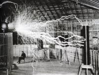
Understanding the laws of electricity and magnetism will make you very powerful. Have you heard of Nikola Tesla? He is a pretty cool guy, and he was a student of electricity and magnetism just like you:
This course requires a good understanding of vector and basic calculus techniques. If you are feel a little rusty on these subjects, I highly recommend that you review the general ideas of vectors and integration before you start reading the material.
Below is a short overview of the topics which we will discuss.
Electricity
We start of with a review of Newton's formula for the gravitation force ($F_g=\frac{GMm}{r^2}$), then learn about electrostatics ($F_e=\frac{kQq}{r^2}$) and discuss three related concepts: the electric potential energy $U_e=\frac{kQq}{r}$, the electric field ($E=\frac{GQ}{r^2}$, $F_e=qE$) and the electric potential ($V=\int E\;dx$, $\vec{E}=\frac{dV}{dx}$).
Circuits
Electrostatic interactions between two points in space A and B take on a whole new nature if a charge-conducting wire is used to connect the two points. Charge will be able to flow from one point to the other along the wire. This flow of charge is called electric current. Current is denoted as $I$[A] and measured in Amperes.
The flow of current is a abstract way of describing moving charges. If you understand that well, you can start to visualize stuff and it will be all simple. The current $I$[A] is the “total number of electrons” passing in the wire in one second.
Electric current can be “accumulated” in charge containers called capacitors.
Magnetism
 Understanding current is very important because each electron by virtue of its motion through
space is creating a magnetic field around it.
The strength of the magnetic field created by each electron is tiny—we could just ignore it.
However if there is a current of 1[A] flowing through the wire, you know how many electrons that makes? It means there is a flow of $6.242 \times 10^{18}$ electrons per second in that wire. This is something we can't ignore. The magnetic field created by this wire will be quite powerful. You can use the magnetic field to build electromagnets (to lift cars in junk yards, or for magnetic locks—when you are fighting the front doors of McConnell to get into Blues Pub after 9PM—you are fighting with the magnetic force). You can also have two magnets push on each other while turning an engine forward—this is called an electric motor (think electric cars).
But hey, you don't have time to learn all of this now. Read a couple of pages and then go practice on the exams from previous years! If you have any problems come ask here: http://bit.ly/XYOhE1 (only on April 21st, 22nd, and 23rd)
Links
Electrostatics
Electrostatics is the study of charge and the electric forces that exist between charges. The same way that the force of gravity exists between any two objects with mass, the electric force (Coulomb force) exists between any two charged objects. We will see, however, that unlike gravity which is always attractive (tends to bring masses closer together), the electrostatic force can sometimes be repulsive (tends to push charges apart).
Electrostatics is a big deal. You are alive right now, because of the electric forces that exist between the amino acid chains (proteins) in your body. The attractive electric force that exists between protons and electrons helps to make atoms stable. The electric force is also an important factor in many chemical reactions.
The study of charged atoms and their chemistry can be kind of complicated. Each atom contains many charged particles: the positively charged protons in the negatively charged electrons. For example, a single iron atom has 26 positively charged particles (protons) in the nucleus and 26 negatively charged electrons in various energy shells surrounding the nucleus. To keep things simple, in this course we will study the electric force and potential energy of only a few charges at a time.
Example: Cathode ray tube
When I was growing up, television sets and computer monitors were bulky objects in which electrons were accelerated and crashed onto a phosphorescent surface to produce the image on the screen. A cathode ray tube (CRT) is a vacuum tube containing an electron gun (a source of electrons). What is the speed of the electrons which produce the image on an old-school TV?
Suppose the Voltage used to drive the electron gun is $4000$[V]. Since voltage is energy per unit charge, this means that each electron that goes through the electron gun will lose the following amount of potential energy \[ U_e = q_e V = 1.602\times10^{-19} \ \times \ 4000 \qquad \text{[J]}. \] In fact the potential energy is not lost but converted to kinetic energy \[ U_e \to K_e = \frac{1}{2}m_e v^2 = \frac{1}{2}(9.109\times10^{-31})v^2, \] where we have used the formula for the kinetic energy of an object with mass $m_e = 9.109\times10^{-31}$ [Kg]. Numerically we get: \[ 1.602\times10^{-19} \ \times \ 4000 = \frac{1}{2}(9.109\times10^{-31})v^2 \qquad \text{[J]}, \] where $v$, the velocity of the electrons, is the only unknown in the equation. Solving for $v$ we find that the elections inside the TV are flying at \[ v = \sqrt{\frac{2 q_e V}{m_e}} = \sqrt{\frac{2 \times 1.602\times10^{-19} \times 4000 }{9.109\times10^{-31}}} = 3.751\times 10^{7} \text{[m/s]}. \] This is pretty fast.
Concepts
- $q$: Electric charge of some particle or object. It is measured in Coulombs $[C]$. If there are multiple charges in the proble we can call them $q,Q$ or $q_1, q_2, q_3$ to distinguish them.
- $\vec{r}$: The vector-distance between two charges.
- $r \equiv |\vec{r}|$: Distance between two charges, measured in meters $[m]$
- $\hat{r} \equiv \frac{ \vec{r} }{ |\vec{r}|}$: A direction vector (unit length vector) in the $\vec{r}$ direction.
- $\vec{F}_e$: Electic force strength and direction, measured in Newtons $[N]$
- $U_e$: The electric potential energy, measured in Joules $[J]=[N*m]$
- $\varepsilon_0=8.8542\ldots\times 10^{-12}$ $\left[\frac{\mathrm{F}}{\mathrm{m}}\right]$: The permittivity of free space, which is one of the fundamental constants of Nature.
- $k_e=8.987551\times 10^9$ $\left[\frac{\mathrm{Nm^2}}{\mathrm{C}^{2}}\right]$: The electric constant. It is related to the permittivity of free space by $k_e=\frac{1}{4 \pi \varepsilon_0}$.
Charge
One of the fundamental properties of matter is charge, which is measured in Coulombs [C]. An electron has the charge $q_e=-1.602\times10^{-19}$ [C]. The electric charge of the nucleus of a Helium atom is $q_{He}=2\times1.602\times10^{-19}$, because it contains two protons and each proton has a charge of $1.602\times10^{-19}$ [C].
Unlike mass, of which there is only one kind, there are two kinds of charge: positive and negative. Using the sign (positive vs. negative) to denote the “type” of charge is nothing more than a convenient mathematical trick. We could have instead called the two types of charges “hot” and “cold”. The important thing is that there are two kinds with “opposite” properties in some sense. In what sense opposite? In the sense of their behaviour in physical experiments. If the two charges are of the same kind, then they try to push each other away, but if the two charges are of different kinds then they will attract each other.
Formulas
Coulomb's law
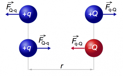 Two point charges $Q$ and $q$ placed at a distance $r$ meters apart will interact
via the electric force.
The magnitude of the electric force is given by the following formula
\[
|\vec{F}_e({r})| = \frac{k_eQq}{r^2} \qquad \text{[N]},
\]
which is known as Coulomb's law.
If the charges are different (one positive and one negative) then the force will be attractive – it will tend to draw the two charges together. If the two charges are of the same sign then the force will be repulsive.
Electric potential energy
Every time you have a force, you can calculate the potential energy associated with that force, which represents the total effect (the integral) of the force over some distance. We now define the electric potential energy $U_e$, i.e., how much potential energy is stored in the configuration of two charges $Q$ and $q$ separated by a distance of $r$. The formula is \[ U({r}) = \frac{kQq}{r} \qquad \text{[J]}, \] which is very similar to the formulate for $|\vec{F}_e(Q,q,r)|$ above, but with a one-over-r relationship instead of a one-over-r-squared.
We learned in mechanics, that often times the most elegant way to solve problems in physics is not to calculate the forces involved directly, but to use the principle of conservation of energy. By simple accounting of the different types of energy: kinetic (K), potential (U) and the work done (W), we can often arrive at the answer.
In mechanics we studied the gravitational potential energy $U_g=mgh$ and the spring potential energy $U_s=\frac{1}{2}kx^2$ associated with the gravitational force and spring force respectively. Now you have a new kind of potential energy to account for: $U_e=\frac{kQq}{r}$.
Examples
Example 1
A charge $Q=20$[$\mu$C] is placed 2.2 [m] away from a second charge $q=3$[$\mu$C]. What will be the magnitude of the force between them? Is the force attractive or repulsive?
Example 2
A charge $Q=6$[$\mu$C] is placed at the origin $(0,0)$ and a second charge $q=-5$[$\mu$C] is placed at $(3,0)$ [m]. What will be the force on $q$. Express your answer as a vector.
If the charge $q$ was placed instead at $(0,3)$[m], what would be the resulting electric vector?
What if the charge $q$ is placed at $(2,4)$[m]. What will be the electric force on $q$ then? Express your answer both in terms of magnitude-and-direction and in component notation.
Example 3
A fixed charge of $Q=3$[$\mu$C] and a movable charge $q=2$ [$\mu$C] are placed at a distance of 30 [cm] apart. If the charge $q$ is released it will fly off into the distance. How fast will it be going when it is $4$[m] away from $Q$?
Explanations
Coulomb's law
The electric force is a vector quantity so the real formula for the electric force must be written as a vector.
Let $\vec{r}$ be the vector distance from $Q$ to $q$. The electric force on the charge $q$ is \[ \vec{F}_e({r}) = \frac{k_eQq}{r^2}\hat{r} \qquad \text{[N]}, \] where $\hat{r}$ is a direction vector pointing away from $Q$. This formula will automatically take care of the direction of the vector in both the attractive and repulsive cases. If $Q$ and $q$ are of the same charge the force will be in the positive $\hat{r}$ direction (repulsive force), but if the charges have opposite sign, the force will be in the negative $\hat{r}$ direction.
In general, it is easier to think of the magnitude of the electric force, and then add the vector part manually by thinking in terms of attractive/repulsive rather than to depend on the sign in the vector equation to figure out the direction for you.
From force to potential energy
The potential energy of a configuration of charges is defined as the negative of the amount of work which would be necessary in order to bring the charges into this configuration: $U_e = - W_{done}$.
To derive the potential energy formula for charges $Q$ and $q$ separated by a distance $R$ in meters, we can imagine that $Q$ is at the origin and the charge $q$ starts off infinitely far away on the $x$-axis and is brought to a distance of $R$ from the origin slowly. The electric potential energy is given by the following integral: \[ \Delta U_e = - W_{done} = - \int_{r=\infty}^{r=R} \vec{F}_{ext}({r}) \cdot d\vec{s}. \] By bringing the charge $q$ from infinitely far away we make sure that the initial potential energy is going to be zero. Just like with all potentials, we need to specify a reference point with respect to which we will measure it. We define the potential at infinity to be zero, so that $\Delta U_e = U_e({R})-U_e(\infty) = U_e({R})-0= U_e({R})$.
OK, so the charge $q$ starts at $(\infty,0)$ and we sum-up all the work that will be necessary to bring it to the coordinate $(R,0)$. Note that we need an integral an integral to calculate the work, because the strength of the force changes during the process.
Before we do the integral, we have to think about the direction of the force and the direction of the integration steps. If we want to obtain the correct sign, we better be clear about all the negative signs in the expression:
- The negative sign in the front of the integral comes from the definition $U_e \equiv - W_{done}$.
- The electric force on the charge $q$ when it is a distance $x$ away
will be $\vec{F}_e({x}) = \frac{k_eQq}{x^2}\hat{x}$.
  Therefore if we want to move the charge $q$ towards $Q$ we have
  to apply an external force $\vec{F}_{ext}$ on the charge in the opposite direction.
  The magnitude of the external force needed
  to hold the charge in place (or to move it towards the origin at a constant speed)
  is given by $\vec{F}_{ext}({x}) = -\frac{k_eQq}{x^2}\hat{x}$.
* The displacement vector $d\vec{s}$ always points in the
  negative direction, since we start from $+\infty$ and move back to the origin.
  Therefore, in terms of the positive $x$-direction the displacements
  are small negative steps $d\vec{s} = - dx\; \hat{x}$.
The negative of the $W_{done}$ from $\infty$ to $R$ is given by the following integral: \[ \begin{align} \Delta U_e & = - W_{done} = - \int_{r=\infty}^{r=R} \vec{F}_{ext}({r}) \cdot d\vec{s} \nl & = -\int_{x=\infty}^{x=R} \left( - \frac{k_eQq}{x^2}\hat{x}\right) \cdot \left( -\hat{x}dx\right) \nl & = - \int_{\infty}^{R} \frac{k_eQq}{x^2} \ (\hat{x}\cdot\hat{x}) \ dx \nl & = - k_eQq \int_{\infty}^{R} \frac{1}{x^2} \ 1 \ dx \nl & = - k_eQq \left[ \frac{-1}{x} \right]_{\infty}^{R} \nl & = k_eQq \left[ \frac{1}{R} - \frac{1}{\infty} \right] \nl & = \frac{k_eQq}{R}. \end{align} \]
So we have that we have \[ \Delta U_e \equiv U_{ef} - U_{ei} = U_e({R}) - U_e(\infty), \] and since $U_e(\infty)=0$ we have derived that \[ U_e({R}) = \frac{k_eQq}{R}. \]
We say that the work done to bring the two charges together is stored in the electric potential energy $U_e({r})$ because if we were to let go of these charges they would fly away from each other, and give back all that energy as kinetic energy.
From potential to force
We can also use the relationship between force and potential energy in the other direction. If I were to tell you that the potential energy of two charges is \[ U({r}) = \frac{k_eQq}{r}, \] then, by definition, the force associated with that potential is given by \[ \vec{F}({r}) \equiv - \frac{dU({r}) }{dr} = \frac{k_eQq}{r^2} \hat{r}. \]
Discussion
More intuition about charge
Opposite charges cancel out. If you have a sphere with $5$[$\mu$C] of charge on it, and you add some negative charge to it, say $-1$[$\mu$C], then the resulting charge on the sphere will be $4$[$\mu$C].
Charged particles will redistribute themselves between different objects brought into contact so as to minimize the repulsive force between them. This means that charge is always maximally spread out over the entire surface of the object. For example, if charge is placed on a metal ball made of conducting material the charge will all go to the surface of the body and will not penetrate into the interior.
As another example, consider two metal spheres that are connected by a conducting wire with a total charge $Q$ placed on the system. Because charge is free to move along the wire, it will end up distributed uniformly over the total area $A =A_1 +A_2$, where $A_1$ and $A_2$ are the surface areas of the two spheres. The surface charge density will be $\sigma = Q/A$ [C/m$^2$]. The charge on each sphere will be proportional to the surface area of the object: \[ Q_1 = \sigma A_1 = \frac{A_1}{A_1+A_2} Q, \qquad Q_2 = \sigma A_2 = \frac{A_2}{A_1+A_2} Q. \qquad \textrm{[C]} \] Note that the $Q_1 + Q_2=Q$ as expected.
Links
Electric field
We will now discuss a new language for dealing with electrostatic problems.
So far we saw that the electric force, $\vec{F}_e$, exists between two charges $Q$ and $q$, and that the formula is given by Coulomb's law $\vec{F}_e=\frac{k_eQq}{r^2}\hat{r}$. How exactly this force is produced, we don't know. We just know from experience that it exists.
The electric field is an intuitive way to explain how the electric force works. We imagine that the charge $Q$ creates an electric field everywhere in space described by the formula $\vec{E} = \frac{k_eQ}{r^2}\hat{r}$ $[N/C]$. We further say that any charge placed in an electric field will feel an electric force proportional to the strength of the electric field. A charge $q$ placed in an electric field of strength $\vec{E}$ will feel an electric force $\vec{F}_e = q \vec{E}=\frac{k_eQq}{r^2}\hat{r}$.
This entire chapter is about this change of narrative when explaining electrostatic phenomena. There is no new physics. The electric field is just a nice way of thinking in terms of cause and effect. The charge $Q$ caused the electric field $\vec{E}$ and the electric field $\vec{E}$ caused the force $\vec{F}_e$ on the charge $q$.
You have to admit that this new narrative is nicer, than just saying that somehow the electric force “happens”.
Concepts
Recall the concepts from electrostatics:
- $q,Q,q_1,q_2$: The electric charge of some particle or object. It is measured in Coulombs $[C]$.
- $\vec{F}$: Electic force strength and direction, measured in Newtons $[N]$
- $U$: Potential energy (electrical), measured in Joules $[J]=[N*m]$
- $\vec{r}$: The vector-distance between two charges.
- $r \equiv |\vec{r}|$: Distance between two charges, measured in meters $[m]$
- $\hat{r}$: A direction vector (unit length vector) in the $\vec{r}$ direction.
In this section we will introduce a new language to talk about the same ideas.
- $\vec{E}$: Electric field strength and direction, measured in $[V/m]$ or Gauss
- $V$: Electric potential, measured in Volts $[V]$
Formulas
Electric field
The electric field caused by a charge $Q$ at a distance $r$ is given by \[ \vec{E}({r}) = \frac{kQ}{r^2}\hat{r} \qquad \text{[N/C]=[V/m]}. \]
Electric force
When asked to calculate the force between two particles we simply have to multiply the electric field times the charge \[ \vec{F}_e({r}) = q\vec{E}({r}) = q\frac{kQ}{r^2}\hat{r} = \frac{kQq}{r^2}\hat{r} \qquad \text{[N]}. \]
Electric potential
The electric potential $V$ (not to be confused with the electric potential energy $U_e$) of a charge $Q$ is given by \[ V({r})= \frac{kQ}{r} \qquad \text{[V]} \equiv \text{[J/C]} \]
Electric potential energy
The electric potential energy necessary to bring charge $q$ to point where an electric potential $V({r})$ exists is given by \[ U_e({r}) = q V({r}) = q\frac{kQ}{r} = \frac{kQq}{r} \qquad \text{[J]}. \]
Relations between the above four quantities
We can think of the electric field $\vec{E}$ as an electric force per unit charge. Indeed the dimensions of the electric field is $\text{[N/C]}$, so the electric field tells us the amount of force that a test charge of $q=1$[C] would feel at that point. Similarly, the electric potential is $V$ is the electric potential energy per unit charge, as can be seen from the dimensions: $\text{[V]}=\text{[J/C]}$.
In the electrostatics chapter we saw that, \[ U_e({R}) = - W_{done} = - \int_{\infty}^R \vec{F}_e({r}) \cdot d\vec{s}, \qquad \qquad \vec{F}_e({r}) = - \frac{dU({r}) }{dr}. \]
An analogous relation exists between the per unit charge quantities. \[ V({R}) = - \int_{\infty}^R \vec{E}({r}) \cdot d\vec{s}, \qquad \qquad \qquad \qquad \ \ \vec{E}({r}) = - \frac{dV({r}) }{dr}. \]
Explanations
Electric potential
A major issue in understanding the ideas of electromagnetism is to get an intuitive understanding of the concept of electric potential $V$. First, there is the naming problem. There are at least four other terms for the concept: voltage, potential difference, electromotive force and even electromotance! Next, we have the possible source of confusion with the concept of electric potential energy, which doesn't help the situation. Perhaps the biggest problem with the concept of electric potential is that it doesn't exist in the real world: like the electric field to which it is related, it is simply a construct of the mind, which we use to solve problems and do calculations.
Despite the seemingly unsurmountable difficulty of describing the nature of something which doesn't exist, I will persist in this endeavour. I want to give you a proper intuition about voltage, because this concept will play an extremely important role in circuits. While it is true that voltage doesn't exist, energy does exist and energy is just $U=qV$. Voltage, therefore, is electric potential energy per unit charge, and we can talk about the voltage in the language of energy.
Every time you need to think about some electric potential, just imagine what would happen to a unit test charge: q=1[C], and then think in terms of energy. If the potential difference between point (a) and point (b) is $V_{ab}=16$[V], this means that a charge of 1[C] that goes from (a) to (b) will gain 16[J] of energy. If you have some circuit with a 3[V] battery in it, then each Coulomb of charge that is pumped through the battery gains $3$[J] of energy. This is the kind of reasoning we used in the opening example in the beginning of electrostatics, in which we calculated the kinetic energy of the electrons inside an old-school TV.
Field lines
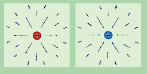 We can visualize the electric field caused by some charge as
electric field lines everywhere around it.
For a positive charge ($Q>0$), the field lines will be leaving it
in all directions towards negative charges or expanding to infinity.
We say that a positive charge is a source of electric field lines
and that a negative charge ($Q<0$) is a sink for electric field lines,
i.e., it will have electric field lines going into it
The diagram on the right illustrates the field lines for two isolated
charges. If these charges were placed next to each other, then
the field lines leaving the (+) charge would all curve around and go into the (-) charge.
Links
[ A guided tour of the electie vield lines ]
http://web.mit.edu/8.02t/www/802TEAL3D/visualizations/electrostatics/index.htm
Electrostatic integrals
The electric field produced by a point charge $Q$ placed at the origin is given by $\vec{E}(\vec{r})=\frac{k_eQ}{r^2}\hat{r}$. What if the charge is not a point but some continuous object? It could be a line-charge, or some charged surface. How would you calculate the electric field produced by such an object $O$?
What you will do is cut up the object into little pieces $dO$ and calculate the electric field produced by each piece and then add up all the contribution. In other words you need to do an integral.
Concepts
- $Q$: the total charge. The units are Coulombs [C].
- $\lambda$: linear charge density. The units are coulombs per meter [C/m].
The charge density of a long wire of length $L$ is $\lambda = \frac{Q}{L}$.
- $\sigma$: the surface charge density. Units are [C/m$^2$].
The charge density of a disk with radius $R$ is $\sigma = \frac{Q}{\pi R^2}$.
  The charge on a sphere of radius $R$ made of conducting material will be concentrated
  on its surface and will have density $\rho =\frac{Q}{4 \pi R^2}$.
* $\rho$: the volume charge density. Units are [C/m$^3$].
  The charge density of a cube of uniform charge and side length $c$ is $\rho = \frac{Q}{c^3}$.
  The charge density of a solid sphere made of insulator with a uniform
  charge distribution will be $\rho = \frac{Q}{\frac{4}{3} \pi R^3}$.
One-over-r-squared quantities:
- $\vec{F}_e$: Electric force.
- $\vec{E}$: Electric field.
One-over-r quantities:
- $U$: electric potential energy.
- $V$: electric potential.
Integration techniques review
Both the formulas for electric force (field) and potential energy (electric potential) contain a denominator of the form $r\equiv |\vec{r}| = \sqrt{x^2 + y^2}$. As you can imagine, these kind of integrals will be quite hairy to calculate if you don't know what you are doing.
But you know what you are doing! Well, you know if you remember your techniques_of_integration. Now I realize we saw this quite a long time ago so a little refresher is in order.
The reason why they make you practice all those trigonometric substitutions is that they will be useful right now. For example, how would you evaluate the integral \[ \int_{-\infty}^{\infty} \frac{1}{(1+x^2)^{\frac{3}{2}} } \ dx, \] if you were forced to – like on an exam question or something. Relax. You are not in an exam. I just said that to get your attention. The above integral may look complicated, but actually you will see that it is not too hard: we just have to use a trig substitution trick. You will see that all that time spent learning about integration techniques was not wasted.
Recall that the trigonometric substitution trick necessary to handle the terms like $\sqrt{1 + x^2}$is to use the identity: \[ 1 + \tan^2 \theta = \sec^2 \theta, \] which comes from $\cos^2 \theta + \sin^2 \theta = 1$ divided by $\cos^2 \theta$.
If we make the substitution $x=\tan\theta$, $dx=\sec^2\theta \ d\theta$ in the above integral we will get \[ 1 + x^2 = \sec^2 \theta. \] But we don't just have $1+x^2$, but $(1+x^2)^{\frac{3}{2}}$. So we need to take the $\frac{3}{2}$th power of the above equation, which is equivalent to taking the square root and then raising to the third power: \[ (1+x^2)^{\frac{3}{2}} = (\sec^2\theta)^{\frac{3}{2}} = \left( \sqrt{ \sec^2\theta} \right)^{3} = (\sec\theta)^{3} = \sec^3\theta. \] Next, we have to calculate the new limits of integration due to the change of variable $x=\tan\theta$. The upper limit $x_f=+\infty$ becomes $\theta_f = \tan^{-1}(+\infty)=\frac{\pi}{2}$ and the lower limit $x_i=-\infty$ becomes $\theta_i = \tan^{-1}(-\infty)=-\frac{\pi}{2}$.
Ok now let's see how all of this comes together: \[ \begin{align} \int_{x=-\infty}^{x=\infty} \frac{1}{(1+x^2)^{\frac{3}{2}} } \ dx &= \int_{ \theta=-\frac{\pi}{2} }^{ \theta=\frac{\pi}{2} } \frac{1}{(1+\tan^2\theta)^{\frac{3}{2}} } \sec^2 \theta \ d\theta \nl &= \int_{ -\frac{\pi}{2} }^{ \frac{\pi}{2} } \frac{1}{\sec^3\theta} \sec^2 \theta \ d\theta \nl &= \int_{ -\frac{\pi}{2} }^{ \frac{\pi}{2} } \cos \theta \ d\theta \nl &= \sin \theta \bigg|_{ -\frac{\pi}{2} }^{ \frac{\pi}{2} } = \sin\left( \frac{\pi}{2} \right) - \sin\left( - \frac{\pi}{2} \right) = 1 - (-1) = 2. \end{align} \]
Exercise
Now I need you to put the book down for a moment and try to reproduce the above steps by practicing on the similar problem: \[ \int_{-\infty}^{\infty} \frac{a}{(a^2+x^2)^{\frac{3}{2}} } \ dx, \] where $a$ is some fixed constant. Hint: substitute $x = a \tan\theta$. This integral corresponds to the strength of the electric field at a distance $a$ from an infinitely long line charge. Ans: $\frac{2}{a}$. We will use this result in Example 1 below, so go take a piece of paper and do it.
The tan substation is also useful when calculating the electric potential, but the denominator will be of the form $\frac{1}{(1+x^2)^{\frac{1}{2}} }$ instead of $\frac{1}{(1+x^2)^{\frac{3}{2}} }$. We show how to compute this integral in Example 3.
Formulas
Let $\vec{E} = ( E_x, E_y )=( \vec{E}\cdot \hat{x}, \vec{E}\cdot \hat{y} )$ be the electric field strength at some point $P$ due to the charge on some object $O$. We can calculate the total electric field by analyzing the individual contribution $dE$ due to each tiny part of the object $dO$.
The total field strength in the $\hat{x}$ direction is given by \[ E_x = \int dE_x = \int_O \vec{E}\cdot \hat{x}\ dO. \]
The above formula is too abstract to be useful. Think of it more as a general statement of the principle that the electric field due to the object as a whole, is equal to sum of the electric field due to its parts.
Charge density
The linear charge density of an object of length $L$ with charge $Q$ on it is \[ \lambda = \frac{Q}{L}, \qquad \textrm{ [C/m] } \] where $\lambda$ is the Greek letter lambda which is also used to denote wavelength.
Similarly the surface charge density is defined as the total charge divided by the total area and the volume charge density as the total charge divided by the total volume: \[ \sigma = \frac{Q}{A} \ \ \ \left[ \frac{\textrm{C}} { \textrm{m}^2} \right], \qquad \rho = \frac{Q}{V} \ \ \ \left[ \frac{ \textrm{C} }{ \textrm{m}^3} \right], \] where $\sigma$ and $\rho$ are the Greek letters sigma and rho.
Examples
Example 1: Electric field of an infinite line charge
Consider a horizontal line charge of charge density $\lambda$ [C/m]. What is the strength of the electric field strength at a distance $a$ from the wire?
The wire has a line symmetry so we can choose any point along the wire, so long as it is $a$[m] away from it. Suppose we pick the point $P=(0,a)$ which lies on the $y$ axis. We want to calculate $\vec{E}({P}) = ( E_x, E_y )=( \vec{E}\cdot \hat{x}, \vec{E}\cdot \hat{y} )$.
Consider first the term $E_y$. It is given by the following integral: \[ \begin{align} E_y & = \int dE_y = \int d\vec{E} \cdot \hat{y} \nl & = \int_{x=-\infty}^{x=\infty} \vec{E}(dx) \cdot \hat{y} \nl & = \int_{x=-\infty}^{x=\infty} \frac{ k_e (\lambda dx)} { r^2} \hat{r} \cdot \hat{y} \nl & = \int_{x=-\infty}^{x=\infty} \frac{ k_e \lambda dx} { r^2} \hat{r} \cdot \hat{y} \nl & = \int_{-\infty}^{\infty} \frac{k_e \lambda}{(a^2+x^2)} ( \hat{r} \cdot \hat{y} ) \ dx \nl & = \int_{-\infty}^{\infty} \frac{k_e \lambda}{(a^2+x^2)} \left( \frac{ a }{ \sqrt{ a^2+x^2} } \right) \ dx \nl & = \int_{-\infty}^{\infty} \frac{k_e \lambda a}{(a^2+x^2)^{\frac{3}{2}} } \ dx. \end{align} \]
We showed how to compute this integral in the review section on integration techniques. If you did as I asked you, you will know that \[ \int_{-\infty}^{\infty} \frac{a}{(a^2+x^2)^{\frac{3}{2}} } \ dx \ = \ \frac{2}{a}. \]
The total electric field in the $y$ direction is therefore given by: \[ E_y = k_e \lambda \int_{-\infty}^{\infty} \frac{ a}{(a^2+x^2)^{\frac{3}{2}} } \ dx \ = \ \frac{ 2 k_e \lambda }{ a }. \]
By symmetry $E_x=0$, since there is an equal amount of charge to the left and to the right of the origin. Therefore, the electric field $\vec{E}({P})$ at the point $P$ at a distance $a$ from the line charge is given by $\vec{E}({P})=(E_x, E_y) = \left( 0, \frac{ 2 k_e \lambda }{ a } \right)$.
Example 2: Charged disk
What is the electric field in the $z$ direction directly above the a disk with charge density $\sigma$[C/m$^2$] and radius $R$ that is lying in the centre of the $xy$-plane?
Example 3: Electric potential of a line charge of finite length
Consider a line charge of length $2L$ and linear charge density $\lambda$. The integral in that case will be \[ \begin{align} \int_{-L}^{L} \frac{1}{ \sqrt{ 1+x^2} } \ dx &= \int \frac{1}{ \sqrt{ 1+\tan^2\theta} } \sec^2 \theta \ d\theta \nl &= \int \frac{1}{\sec\theta} \sec^2 \theta \ d\theta \nl &= \int \sec \theta \ d\theta. \end{align} \] To proceed we need to remember a sneaky trick, which is to use the substitution $u = \tan\theta +\sec\theta$, $du=\sec^\theta + \tan\theta\sec\theta$ and to multiply top and bottom by $\tan\theta +\sec\theta$. \[ \begin{eqnarray} \int \sec(\theta) \, dx &=& \int \sec(\theta)\ 1 \, d\theta \nl &=& \int \sec(\theta)\frac{\tan(\theta) +\sec(\theta)}{\tan(\theta) +\sec(\theta)} \ d\theta \nl &=& \int \frac{\sec^2(\theta) + \sec(\theta) \tan(\theta)}{\tan(\theta) +\sec(\theta)} \ d\theta\nl &=& \int \frac{1}{u} du \nl &=& \ln |u| \nl &=& \ln |\tan(\theta) + \sec(\theta) | \nl &=& \ln \left| x + {\sqrt{ 1 + x^2} } \right| \bigg|_{-L}^L \nl &=& \ln \left| L + {\sqrt{ 1 + L^2}} \right| - \ln \left| -L + {\sqrt{ 1 + L^2} } \right| \nl &=& \ln \left| \frac{ L + {\sqrt{ 1 + L^2} } } { -L + {\sqrt{ 1 + L^2} } } \right|. \end{eqnarray} \]
Exercise: The above calculation is showing the important calculus core of the problem. The necessary physical constants like $\lambda$ (charge density) and $a$ (distance from wire) are missing. Add them to obtain the final answer. You can check your answer in the link below.
Discussion
If you find the steps in this chapter complicated, then you are not alone. I had to think quite hard to get all the things right so don't worry: you won't be expected to do this on an exam on your own. In a homework problem maybe.
The important things to remember is to split the object $O$ into pieces $dO$ and then keep in mind the vector nature of $\vec{E}$ and $\vec{F}_e$ (two integrals: one for the $x$ component of the quantity and one for the $y$ component).
An interesting curiosity is that the electric potential at a distance $a$ from an infinitely long wire is infinite. The potential scales as $\frac{1}{r}$ and so integrating all the way to infinity makes it blow up. This is why we had to choose a finite length $2L$ in Example 3.
Links
Gauss' law
We saw in the previous chapters that the electric field $\vec{E}$ is a useful concept in order to visualize the electromagnetic effects produced by charged objects. More specifically, we imagined electric field lines which are produced by positive charges $+Q$ and end up on negative charges $-Q$. The number of field lines produced by a charge $+2Q$ is the double of the number of field lines produced by a charge $+Q$.
In this section, we learn how to count the number of field lines passing through a surface (electric flux) and infer facts about the amount of charge that the surface contains. The relationship between the electric flux leaving a surface and the amount of charge contained in that surface is called Gauss' law.
Consider the following reasoning. To keep the numbers simple, let us say that a charge of 1[C] produces exactly 10 electric field lines. Someone has given you a closed box $B$ with surface area $S$. Using a special instrument for measuring flux, you find that there are exactly 42 electric field lines leaving the box. You can then infer that there must be a net charge of 4.2[C] contained in the box.
In some sense, Gauss' law is nothing more than a statement of the principle of conservation of field lines. Whatever field lines are created within some surface must leave that surface at some point. Thus we can do our accounting in two equivalent ways: either we do a volume accounting to find the total charge inside the box, or we do a surface accounting and measure the number of field lines leaving the surface of the box.
Concepts
- $Q$: Electric charge of some particle or object. It is measured in Coulombs $[C]$.
- $S$: Some closed surface in a three dimensional space. ex: box, sphere, cylinder.
- $A$: The area of the surface $S$.
- $dA$: A small piece of surface area used for integration. We have that $A=\int_S dA$.
- $d\vec{A}=\hat{n}dA$: A oriented piece of area, which is just $dA$ combined with
a vector $\hat{n}$ which points perpendicular to the surface at that point.
- $\Phi_S$= The electric flux is the total amount of electric field $\vec{E}$ passing through the surface $S$.
- $\varepsilon_0=8.8542\ldots\times 10^{-12}$ $\left[\frac{\mathrm{F}}{\mathrm{m}}\right]$: The permittivity of free space, which is one of the fundamental constants of Nature.
Instead of a point charge $Q$, we can have charge spread out:
- $\lambda$: linear charge density. The units are coulombs per meter [C/m].
The charge density of a long wire of length $L$ is $\lambda = \frac{Q}{L}$.
- $\sigma$: the surface charge density. Units are [C/m$^2$].
The charge density of a disk with radius $R$ is $\sigma = \frac{Q}{\pi R^2}$.
- $\rho$: the volume charge density. Units are [C/m$^3$].
The charge density of a cube of uniform charge and side length $c$ is $\rho = \frac{Q}{c^3}$.
Formulas
Volumes and surface areas
Recall the following basic facts about volumes and surface areas of some geometric solids. The volume of a parallelepiped (box) of sides $a$, $b$, and $c$ is given by $V=abc$, and the surface area is given by $A=2ab+2bc+2ac$. The volume of a sphere of radius $r$ is $V_s=\frac{4}{3}\pi r^3$ and the surface area is $A_s=4\pi r^2$. A cylinder of height $h$ and radius $r$ has volume $V_c=h\pi r^2$, and surface area $A_c=(2\pi r)h + 2 (\pi r^2)$.
Electric flux
For any surface $S$, the electric flux passing through $S$ is given by the following vector integral \[ \Phi_S = \int_S \vec{E} \cdot d\vec{A}, \] where $d\vec{A}=\hat{n} dA$, $dA$ is a piece of surface area and $\hat{n}$ points perpendicular to the surface.
I know what you are thinking “Whooa there Johnny! Hold up, hold up. I haven't seen vector integrals yet, and this expression is hurting my brain because it is not connected to anything else I have seen.” Ok you got me! You will learn about vector integrals for real in the course Vector Calculus, but you already have all the tools you need to understand the above integral: the dot product and integrals. Besides, in first electromagnetism course you will only have to do this integral for simple surfaces like a box, a cylinder or a sphere.
In the case of simple geometries where the strength of the electric field is constant everywhere on the surface and its orientation is always perpendicular to the surface (\hat{E}\cdot\hat{n}=1) the integral simplifies to: \[ \Phi_S = \int_S \vec{E} \cdot d\vec{A} = |\vec{E}| \int_S (\hat{E} \cdot \hat{n}) dA = |\vec{E}| \int_S 1 dA = |\vec{E}|A. \]
In all problems and exams in first year electricity and magnetism we will
have $\Phi_S = |\vec{E}|A$ or $\Phi_S = 0$ (if $\vec{E}$ is parallel to the surface),
so essentially you don't have to worry about the vector integral.
I had to tell you the truth though, because this is the minireference way.
Gauss' law
Gauss' law states that the electric flux $\Phi_S$ leaving some closed surface $S$ is proportional to the total amount of charge $Q_{in}$ enclosed inside the surface: \[ \frac{Q_{in}}{\varepsilon_0} = \Phi_S \equiv \int_S \vec{E} \cdot d\vec{A}. \] The proportionality constant is $\varepsilon_0$, the permittivity of free space.
Examples
Sphere
Consider a spherical surface $S$ of radius $r$ enclosing a charge $Q$ at its centre. What is the strength of the electric field strength, $|\vec{E}|$, on the surface of that sphere?
We can find this using Gauss' law as follows: \[ \frac{Q}{\varepsilon_0} = \Phi_S \equiv \int_S \vec{E} \cdot d\vec{A} = |\vec{E}| A = |\vec{E}| 4 \pi r^2. \] Solving for $|\vec{E}|$ we find: \[ |\vec{E}| = \frac{Q}{4 \pi \varepsilon_0 r^2} = \frac{k_eQ}{r^2}. \] I bet you have seen that somewhere before. Coulomb's law can be derived from Gauss' law, and this is why the electric constant is $k_e=\frac{1}{4\pi \epsilon_0}$.
Line charge and cylindrical surface
Consider line charge of charge density $\lambda$ [C/m]. Imagine a charged wire which has 1[C] of charge on each meter of it. What is the strength of the electric field strength at a distance $r$ from the wire?
This is a classical example of a bring your own surface (BYOS) problem: the problem statement didn't mention any surface $S$, so we have to choose it ourselves. Let $S$ be the surface are of a cylinder of radius $r$ and height $h=1$[m] that encloses the line charge at its centre. We now write down Gauss' law for that cylinder: \[ \begin{align} \frac{\lambda (1 [\textrm{m}])}{\varepsilon_0} & = \Phi_S \equiv \int_S \vec{E} \cdot d\vec{A} \nl & = \vec{E}({r}) \cdot \vec{A}_{side} + \vec{E}_{top} \cdot \vec{A}_{top} + \vec{E}_{bottom} \cdot \vec{A}_{bottom} \nl & = (|\vec{E}|\hat{r}) \cdot \hat{r} 2 \pi r (1 [\textrm{m}]) + 0 + 0 \nl & = |\vec{E}| (\hat{r}\cdot \hat{r}) 2 \pi r (1 [\textrm{m}]) \nl & = |\vec{E}| 2 \pi r (1 [\textrm{m}]). \end{align} \]
Solving for $|\vec{E}|$ in the above equation we find \[ |\vec{E}| = \frac{ \lambda }{ 2 \pi \varepsilon_0 r } = \frac{ 2 k_e \lambda }{ r }. \]
Which you should also have seen before (Example 1 in electrostatic_integrals ).
Electric field inside a capacitor
Assume you have two large metallic plates of opposite charges (a capacitor). The (+) plate has charge density $+\sigma$[C/m$^2$] and the (-) plate has $-\sigma$[C/m$^2$]. What is the strength of the electric field between the two plates?
Consider first a surface $S_1$ which makes a cross section of area $A$ that contains sections of both plates. This surface contains no net charge, so by Gauss' law, we conclude that there are no electric field lines entering or leaving this surface. An electric field $\vec{E}$ exits between the two plates and nowhere outside of the capacitor. This is, by the way, why capacitors are useful: since they store a lot of energy in a confined space.
Consider now a surface $S_2$ which also makes a cross section of area $A$, but only goes halfway through the capacitor, enclosing only the (+) plate. The total charge inside the surface $S_2$ is $\sigma A$, therefore by Gauss' law \[ \frac{\sigma A}{\varepsilon_0} = |\vec{E}|A, \] we conclude that the electric field strength inside the capacitor is $|\vec{E}| = \frac{\sigma }{\varepsilon_0}$.
We will see in capacitors, that this result can also be derived by thinking of the electric field as the spacial derivative of the voltage on the capacitor. You should check that the two approaches lead to the same answer for some physical device with area $A$, plate separation $d$.
Explanations
Surface integral
The flux $\Phi_S$ is a measure of the strength of the electric field lines passing through the surface $S$. To compute the flux, we need the concept of directed area, that is, we split the surface $S$ into little pieces of area $d\vec{A} = \hat{n} dA$ where $dA$ is the surface area of a little piece of surface and $\hat{n}$ is a vector that points perpendicular to the surface. We need this kind of vector to calculate the flux leaving through $dA$: \[ d\Phi_{dA} = \vec{E} \cdot \hat{n} dA, \] where the dot product is necessary to account for the relative orientation of the piece surface are and the direction of the electric field. For example if the piece-of-area-perpendicular vector $\hat{n}$ points outwards on the surface and an electric field of strength $|\vec{E}|$ is leaving the surface then the flux integral will be positive. If on the other hand electric field lines are entering the surface, the integral will come out negative since $\vec{E}$ and $d\vec{A}$ will point in opposite directions. Of particular importance are surfaces where the electric field lines are parallel to the surface: in that case $\vec{E} \cdot \hat{n} dA = 0$.
Implications
Have you ever wondered why the equation for the strength of the electric field $|\vec{E}|(r )$ at a function of the distance $r$ is given by the formula $|\vec{E}(r )|=\frac{kQ}{r^2}$? Why is it one-over-$r$-squared exactly? Why not one over $r$ to the third power or the seventh?
The one-over-$r$-squared comes from Gauss' law. The flux $\Phi$ is a conserved quantity in this situation. The field lines emanating from the charge $Q$ (assumed $Q$ is positive) flow outwards away from the charge and uniformly in all directions. Since we know that $\Phi = |\vec{E}|A_s$, then it must be that that $|\vec{E}| \propto 1/A_s$. The surface area of sphere is
Imagine now applying Gauss' law to a small surface which tightly wraps the charge (small $r$) and a larger spherical surface (big $r$). The total flux of electric field through both surfaces is the same. The flux near the charge is due to a very strong electric field that flows out of a small surface area. The flux far away from the charge is due to a very weak field over a very large surface area.
Discussion
So what was this chapter all about? We started with crazy stuff like vector integrals (more specifically surface integrals) denoted by fancy Greek letters like $\Phi$, but in the end we derived only three results which we already knew. What is the point?
The point is that we have elevated our understanding from the formula level to a principle. Gauss' law is a super-formula: a formula that generates formulas. The understanding of such general principles that exist in Nature is what physics is all about.
Circuits
Electric circuits are contraptions in which electric current flows through various pipes (wires) and components (resistors, capacitors, inductors, on-off switches, etc.). Because the electric current cannot escape the wire, it is forced to pass through each of the components along its path.
Your sound system is a circuit. Your computer power supply is a circuit. Even the chemical reactions involved in neuronal spiking can be modelled as an electric circuit.
Concepts
$I$: the electric current. It flows through all circuit components. We measure current in Amperes $[A]$.
  We use wires to guide the flow of currents: to make them go where we want.
* {{ :electricity:circuit-element-voltage.png|}}
  $V$: the electric potential difference between two points. We say //voltage// for short instead of "electric potential difference". There is no notion of "absolute" voltage, we only measure potential difference between //two// points. Thus if you should always label a (+) side and a (-) side when reporting a voltage. Conveniently, the unit of Voltage is the Volt [V], after Volta.
* $P$: the power consumed or produced by some component. Measured in Watts [W].
* $R$: the //resistance// value of a resistor. For resistors, the voltage across the leads is linearly related to current flowing in the resistor. We call //resistance// the ratio between the voltage and the current:
  \[
    R=\frac{V}{I}.
  \]
  We measure resistance in Ohms [$\Omega$].
Circuit components
The basic building blocks of circuits are called electric components. In this section we will learn how to use the following components.
\[ V_{\text{wire}} = \text{any}, \quad \qquad I_{\text{wire}} = \text{any} \]
Battery: This is a voltage source. Can provide any current, but always keeps a constant voltage of V volts.
  \[
    V_{\text{batt}} = V, \qquad \qquad I_{\text{batt}} = \text{any}
  \]
Current source: This device pushes a constant current of $I$ [A], no matter what circuit it is connected to. The current source is allowed to have any voltage across its terminals.
  \[
    V_{\text{source}} = \text{any}, \quad \qquad I_{\text{source}} = I
  \]
Resistor: Can carry any current $I$, and has a voltage across its terminals of $V=RI$ where $R$ is the resistance measured in Ohmns [$\Omega$].
  \[
    V_{\text{resistor}} = I_{\text{resistor}}R, \qquad \qquad I_{\text{resistor}} = \frac{V_{\text{resistor}}}{R}
  \]
  The energy of the electrons (the voltage) right before entering the resistor is $IR$ [V] higher than when they leave the resistor. It is important to label the positive and negative terminals of the resistor. The positive terminal is where the current enters, the negative where the current leaves.
An on-off switch.
  When the switch is //off// (we also say //the switch is open// like in the figure on the right),
  then the two pieces of wires are disconnected and no current is allowed
  to flow through.
  When the switch is //on// (or //closed//), then it acts like a piece of wire
  and will let current through.
General principles
Ohm's law
The voltage across the terminals of a resistor is proportional to the current
flowing through. The more current flowing through, the more voltage will be dropped.
The constant of proportionality is called resistance of the element.
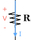 \[
V= IR, \qquad \text{or} \qquad I = \frac{V}{R}, \qquad \text{or} \qquad R = \frac{V}{I}
\]
This is obey Ohm's law.
Electric power
The power consumed by an electric component is given by \[ P = V I, \] where $I$ is the current going into the (+) terminal of the device. The logic behind this formula is as follows. Each electron passing through the device will have lost $V$ volts of electric potential by passing through the device, and the more of them that are flowing (high current) then more power will be consumed.
For batteries, usually the current leaves the (+) terminal instead of entering it, which is equivalent to saying that a negative current flows into the (+) terminal. The expression for the power consumed will therefore be negative: which makes sense since batteries supply energy to the circuit.
For resistors, the current always flows into the (+) side, so power is always consumed. Furthermore, since we know that $V=IR$, we can rewrite the power formula in two other equivalent forms: \[ P = V I, \qquad P = \frac{V^2}{R} \qquad P = RI^2. \] These forms are useful when only the current or the voltage of a resistor is known.
Kirchhoff's loop law
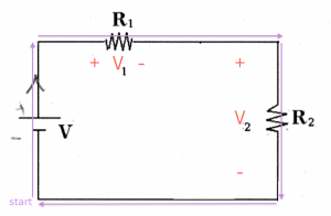 Let's follow the life of a charge going around in the circuit.
It's kind of like a reality show, but with a really simple character.
The journey of the charge begins at $\color{blue}{\text{start}}$, and we will say that the electric potential of this point is $0$[V].
The charge goes up and as it passes through the battery it gains $V$ volts of potential.
We know this, because this is what batteries do: they take charges at the (-) terminal and push them out of (+) terminal with $V$ volts more electric potential.
Next the charge goes right and passes through the resistor $R_1$. The result of this is a change of $-V_1$ in electric potential. This is because the charge dissipated some energy as it passed thought the resistor.
Some more voltage is dropped as it passes through the second resistor. The change in potential is $-V_{2}$,
because the change enters the (+) side and leaves at the (-) side.
Then the charge comes back to $\color{blue}{\text{start}}$, and so its potential must be zero again:
\[
0 + V - V_1 - V_{2} = 0.
\]
By doing this imaginary journey we have established a connection between the battery voltage and the total voltage dropped in the circuit loop.
Kirchhoff's law says that the sum of the voltage gains and drops along any loop must add up to zero: \[ \sum_{\text{loop}} V_i = 0. \]
Kirchhoff current law
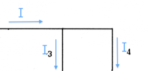 If you have one current going into a junction, and two currents leaving the junction then:
\[
I = I_3 + I_4.
\]
This is implied by conservation of charge: charge can't be created or destroyed so the sum of the currents coming into a junction, must equal the sum of the currents leaving the junction:
\[
\sum I_{\text{in}} = \sum I_{\text{out}}.
\]
Resistances in series
 If you have several resistors attached together in series, then the
equivalent resistance of the three resistors is
\[
R_{eq} = R_1 + R_2 + \ldots + R_n.
\]
Note that in this configuration the same current flows through all the resistors.
Example 1
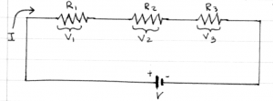 Suppose you have connected three resistors $R_1=1[\Omega]$, $R_2=3[\Omega]$ and $R_3=5[\Omega]$ in series to a 16[V] battery.
Q: What is the equivalent resistance of the circuit?
A: The equivalent resistance that the battery sees is $R_{eq}=R_1+R_2+R_3 = 8[\Omega]$.
Q: What will be the current $I$ in the circuit?
A: The current flowing in the circuit can be found by using Ohm's law V=IR. In this case $I=\frac{V}{R}=\frac{16}{8} = 2$[A].
Q: What is the voltage drop across $R_3$?
A: The voltage is $V_3=IR_3=(2[A])(5[\Omega]) = 10$[V].
Resistances in parallel
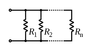 For resistors in parallel, the equivalent resistance is:
\[
R_{eq} = \frac{1}{\frac{1}{R_1}+\frac{1}{R_2}+\ldots+\frac{1}{R_n}}.
\]
Because all the resistors are connected to the same (+) and (-)
endpoints, they will all have the same voltage across them.
When there are just two resistors in parallel, the equation simplifies to: \[ R_{eq} = \frac{1}{ \frac{1}{R_1}+\frac{1}{R_2} } = \frac{R_1R_2}{R_1+R_2}. \] We sometimes denote the equivalent resistance of $R_1$ and $R_2$ in parallel as $R_1 \| R_2$.
Example 2
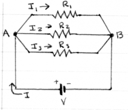 Suppose you have connected three resistors $R_1=1[\Omega]$, $R_2=3[\Omega]$ and $R_3=5[\Omega]$ in parallel to a 16[V] battery.
Q: What is the equivalent resistance of the circuit?
A: The equivalent resistance as seen by the battery is: $R_{eq}=\left(\frac{1}{1}+\frac{1}{3}+\frac{1}{5}\right)^{-1}$.
We can calculate it by finding the least common denominator.
$R_{eq} = \left(\frac{15}{15}+\frac{5}{15}+\frac{3}{15}\right)^{-1} =
\left(\frac{23}{15}\right)^{-1}=\frac{15}{23}\approx 0.652[\Omega]$.
Q: What will be the current $I$ drawn from the battery?
A: The battery will supply $I=\frac{V}{R_{eq}}$ Amperes.
In this case $I=\frac{V}{R}=\frac{16}{15/23} = 368/15\approx 24.533$[A].
Q: What are the currents $I_1$, $I_2$ and $I_3$ flowing through each resistor?
A: All three resistors are connected across the same voltage $V=16$[V], so we can use Ohm's law on each individually to find the current. $I_1 = \frac{16}{1}=16$[A], $I_1 = \frac{16}{3}\approx 5.333$[A],
and $I_3 = \frac{16}{5}=3.2$[A]. Note that $I_1+I_2+I_3=I$ as required by Kirchhoff's current law for points A and B.
Q: What is the voltage drop across $R_3$?
A: This is a trick question. $R_3$ is connected across the $16$[V] battery, so the voltage drop across it is 16[V].
Units
I want to also give you some intuition about the quantities we normally see in circuit. Most electronics work with milliamperes [mA] and small voltages like 3V or 5V. On the other hand, an electric radiator can draw about 10$[A]$ or current easily. The voltage that is used for power transport over long distances is on the order of 50000$[V]$ – this is why they call them high-voltage lines.
Worked example
You have in your hands the following circuit. There is a voltage source of $V$[V] and four loads $R_1$, $R_2$, $R_3$ and $R_4$, which could be light bulbs, heating elements or any other kind of device. Assume that the value of the resistances are given to you and you are given the following task: Find the value of of the current flowing through resistor $R_4$?
First observe that the switch $S$ is open, so effectively that entire branch of the circuit is completely disconnected and we can ignore it. We have to find all the currents and voltages in this circuit. To do this we will use Ohm's law ($V=IR$) three times, each time applying the rule to different sections of the circuit. Let's get started.
Step 1: The first step is to simplify the circuit. Since $R_3$ and $R_4$ are in parallel, we can replace them with their equivalent resistance: \[ R_{34} = \frac{R_3R_4}{R_3+R_4}. \] The equivalent circuit looks much simpler now, and in particular there is only one current: the current $I$ flowing around the loop.
Step 2: To calculate the value of the current, we divide the value of the voltage source $V$ by the total resistance of the circuit $R_{tot} = R_1 + R_{34}$: \[ I = \frac{V}{R_1+R_{34}} = \frac{V_{tot}}{R_{tot}}. \]
Step 3: Now that we know the current flowing in this loop we can compute the voltages dropped on $R_1$ and $R_{34}$ respectively. To calculate these voltages, we use $V=IR$ again: \[ V_1 = IR_1 = \frac{V}{R_1+R_{34}}R_1, \qquad V_{34} = IR_{34} = \frac{V}{R_1+R_{34}}R_{34}. \]
Step 4: It is time to de-simplify the circuit and replace the equivalent resistance $R_{34}$ with the real circuit which had $R_3$ and $R_4$ in parallel. In doing so, we introduce two new variables $I_3$ and $I_4$, the currents flowing in each branch of the circuit.
Step 4: In this last step we have to find the current $I_4$. This is easy to do since we know the value of the voltage $V_{34}$ across it leads. Indeed we can find both currents $I_3$ and $I_4$ by using the $V=IR$ formula again: \[ I_3 = \frac{V_{34}}{R_3}, \qquad I_4 = \frac{V_{34}}{R_4}. \] Note that the two resistors in parallel have the same voltage across them.
We were able to carry out the entire calculation using variables. This is a good approach to follow, rather than solving with the numerical values of the resistors. Let's say that your teacher wants you to answer the problem for a particular set of parameters: the voltage source has $V=7[V]$ and $R_1=3[\Omega]$, $R_2=356[\Omega]$, $R_3=8[\Omega]$ and $R_4=8[\Omega]$. In that case we would have: \[ R_{34} = 8\|8 = \!\!\frac{8\times 8}{8\ + \ 8} = 4[\Omega],\ \ I = \frac{7}{3+4}=1[A], \ \ V_{34} = IR_{34} = 4[V], \ \ I_4 = \frac{V_{34}}{R_4} = \frac{4}{8} = 0.5[A]. \]
Bonus Step: Since we have all the voltages and currents calculated, let's calculate the power $P=IV$ consumed by the different elements of the circuit.
We first calculate the power consumed by the battery. We have to put a negative current into the equation for power, since the current $I$ is leaving the (+) terminal: \[ P_{\text{batt}} = IV = (-1[A])(7[V])=-7[W]. \] We say that the battery generates 7[W], since negative power consumed, means that this device is actually inputting power into the circuit rather than consuming it.
For the resistors we can use any one of these expressions: $P=IV=IR^2=V^2/R$. \[ P_1 = I^2R_1 = 3[W], \ P_2 = 0, \ P_3 = I_3V_{34} = 0.5[A]4[V]=2[W], \ P_4 = I_4V_{34} = 2[W]. \] Note that we have overall conservation of power in the circuit. The battery produces 7[W] and the resistors consume a total of 7[W].
Electric measurement tools
How do we measure all these things that we have been plugging into equations? Currents, voltages, resistances: how do we see them?
Voltmeter
   ________
  |        |
  | [   V] |
  |        |
  | +    - |
  |_|____|_|
    |    |
    \==  \_==
The voltmeter measures the voltage difference between two points in the circuit. The voltage measured tell us how much electric potential energy the electrons gain (or lose) by going from the point attached to + to the point attached to -.
Observations:
- If you connect the two leads + and - together, then you will measure 0 [V].
There is no potential difference, since you are at the same point.
- Say you have an AA battery. If you connect a voltmeter (+) to the battery (+) and the voltmeter (-) to the battery (-), the voltmeter will report 1.5V. This means that an electric charge gains 1.5V of potential energy when it goes from one terminal to the other.
- If you connect the voltmeter (+) to the battery (-) and vice versa, then it will read -1.5V.
- If you connect 10 AA batteries head to tail, then the voltage between the (+) of the first one and the (-) of the last the voltmeter will measure 15[V].
How does a voltmeter work? It diverts a tiny quantity of electrons from the main circuit and measures the change in their energy as they pass from the (+) side to the (-) side.
Amperemeter
    |
   _|______
  | +      |
  |        |
  | [   A] |
  |        |
  |      - |
  |______|_|
         |
         \____
To measure the current in some wire, you need to open the circuit and connect an ampermeter in series. Thus, the current you are trying to measure will have to pass through the ampermeter and you will be able to measure how big that current is.
Ohmmeter
If you want to measure the resistance, then you use an Ohm-meter.
   ________
  |        |
  | [   Ω] |
  |        |
  |        |
  |_|____|_|
    |    |
    \    \___
     \___
If you put the two leads across a resistor, this device will compute the equivalent resistance $R_{eq}$ for that device. It does this by passing a small current through, and measuring the resulting voltage. The Ohmmetter is essentially the combination of a voltmeter and an ampermeter and it reports the ratio $R_{eq} = V_{\text{resulting}}I_{\text{pushed}}$.
If you want to measure the resistance of a resistor, you have to disconnect it from the rest of the circuit. If you don't do that, the Ohmmeter will report the effective resistance of the whole circuit.
Discussion
We have seen how to solve simple circuits involving resistors. In the next chapter, we will learn how to deal with more complicated arrangements of resistors and in the chapters after that we can learn about the properties of new circuit elements like capacitors or inductors.
Links
Capacitors
Capacitors are used to store electric energy. We can also call them condensers, since they condense a lot of charge in one place. We saw already that the capacity of an object to store electric charge is proportional to the surface area the object. To store a lot of charge, therefore, you need large objects, but it is impractical to carry around huge metallic spheres.
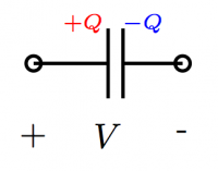 A more successful way to store charge is the parallel
plate capacitor which has two plates: one side will
store positive charge and the other negative charge.
We can imagine that some a voltage source of $V$[V] is
used to charge the capacitor by stripping electrons
from the (+) side and moving them over to the (-) side.
When the capacitor is disconnected, it will then store
the charge $+Q$ and $-Q$ on its plates.
The capacitance, $C$[F], is a property of the capacitor
which tells us how much charge it will store for a
given voltage $V$ applied to it: $Q=CV$.
Inside every camera there is a simple electronic circuit that uses a capacitor in order to provide a sudden burst of electricity to the light bulb. When you turn on the flash, the circuit starts by connecting the capacitor to the battery in order to charge the capacitor. If your camera uses two AA batteries, then the charging voltage will be 3[V]. During this time, a blinking yellow light will indicate to you that you should wait. The camera is saying “Wait a minute please while I pump some charge into the capacitor”. When the charging is done and you take the picture, all the electric energy stored in the capacitor will be released in one burst (a current spike) into the flash lightbulb thus resulting in moment of super high light intensity unlike one that would be possible if you simply connected the light bulb to the batteries.
Concepts
- $Q$: The amount of charge on the capacitor. The (+) plate will have charge $+Q$[C],
while the (-) plate will have $-Q$[C].
- $V$: The voltage access the capacitor.
- C: the capacitance of the capacitor.
For a parallel plate capacitor, the capacitance $C$ is a function of the following physical properties of the capacitor:
- $A$: the area of the plates.
- $d$: the distance between the plates.
- $\varepsilon=\varepsilon_r\varepsilon_0$: The permittivity of the material between the plates,
where $\varepsilon_0$ is the permittivity of free space and $\varepsilon_r$ is the relative permittivity
of the material.
We will also study the electric potential ($V$) and the electric field $\vec{E}$ at different points in the capacitor:
- $x$: a variable that indicates the distance from the (+) plate inside the capacitor. $x\in[0,d]$.
- $V(x)$: the voltage (electric potential) in the capacitor at position $x$.
- $\vec{E}(x)$: the electric field at position $x$ inside the capacitor.
To study the process of charging and discharging, we must describe the state of the capacitor as a function of time:
- $q(t)$: the charge on the (+) plate as a function of time.
- $v_c(t)$: the voltage between the plates of the capacitor as a function of time.
- $i_c(t)$: the current entering the (+) side of the capacitor.
Formulas
Definition of capacitance
The charge stored on a capacitor of capacitance $C$[F] when charged to a voltage $V$[V] is given by: \[ Q = CV. \] The units of capacitance are Farads [F]=[C/V].
Physics properties
Consider a capacitor of area $A$, plate separation $d$ and material of dielectric constant $\varepsilon$ inserted between the plates. The capacitance of such a device is \[ C = \frac{\epsilon A}{d}. \qquad [\textrm{F}] \]
Voltage-current relationship
Because charge cannot simply be created from thin air, any amount of charge that appears on the (+) plate must have come into the capacitor as an electric current of charge. We define the current entering the capacitor $i_c(t)$ as the derivative of the charge on in the capacitor: \[ i_c(t) \equiv \frac{dq(t)}{dt}. \qquad [\textrm{A}] = [\textrm{C}/\textrm{s}] \] The bigger the current flowing into the (+) side of the capacitor, the faster the charge will build up. By using the definition of capacitance $Q=CV$, we also get the following relation \[ i_c(t) = C \frac{dv_c(t)}{dt}, \] which relates $i_c(t)$ and $v_c(t)$ the two quantities which we usually measure in circuits.
Another way of looking at the above differential relation is to say that the charge on the plate, $q(t)$, is equal to the initial charge $q(0)$ plus the sum (integral) of all the current that has gone into the capacitor: \[ q(t) = q(0) \ + \ \int_0^t i_c(\tau) d\tau. \] We can use the relation $Q=CV$ rewritten as $V=\frac{1}{C}Q$ to obtain the equation: \[ v_c(t) = v_c(0) \ + \ \frac{1}{C}\int_0^t i_c(\tau) d\tau. \]
Recall from calculus that a necessary condition for a function to have a well defined derivative is for the function to be continuous. The fact that we have $i_c(t) = C \frac{dv_c(t)}{dt}$ means that the capacitor voltage $v_c(t)$ must be continuous: it cannot suddenly jump in value or else this would correspond to infinite amount of current, which is impossible. Because of this voltage-smoothing property of capacitors, they are used in electronics and sound equipment in order to filter out voltage spikes.
Energy stored in a capacitor
The energy stored in a capacitor is given by \[ E = \frac{1}{2} Q V = \frac{1}{2} \frac{Q^2}{C} = \frac{1}{2} CV^2. \qquad [\textrm{J}] \]
Equivalent capacitors
We will now study what happens if we connect multiple capacitors together. We will see two formulas for finding the equivalent capacitance of the capacitors taken together as a whole.
Capacitors in parallel
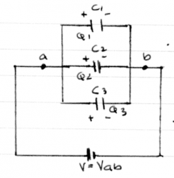 If you take several capacitors and connect them to the
same voltage source we get the parallel configuration.
In this setup, all the capacitors will have the same voltage
across their plates:
\[
V_1 = V_2 = V_3 = V_{ab}.
\]
Effectively, you have build a
capacitor that has a combined surface area of the
three capacitors.
It should not be a surprise that the formula for
the equivalent capacitance of the three capacitors
taken together is
\[
C_{eq} = C_1 + C_2 + C_3.
\]
Furthermore, because we know the voltage on each of the capacitors is $V_{ab}$ we can use $Q=CV$ to find the charge on each of the capacitors: \[ Q_1 = C_1 V_{ab}, \qquad Q_2 = C_2 V_{ab}, \qquad Q_3 = C_3 V_{ab}. \]
Capacitors in series
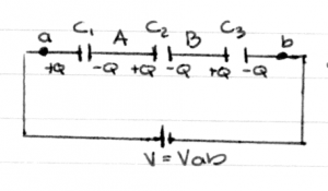 Consider now three capacitors connected one after the other.
We say that the capacitors are connected in series.
Consider the region labelled (A), which consists
of the (-) plate of $C_1$ and the (+) plate of $C_2$.
Because the region (A) started off initially uncharged,
it must be so after the battery is connected. Whatever
negative charge exists on the (-) plate of $C_1$,
therefore, must have comes from the (+) plate of $C_2$.
The same is true for the region (B).
This means that the charge on all the capacitors must
be the same:
\[
Q_1 = Q_2 = Q_3 = Q.
\]
Since the capacitors are connected in series, the battery voltage $V_{ab}$ must be shared between all the capacitors. By Kirchhoff's voltage rule we have that: \[ V_{ab} = V_1 + V_2 + V_3. \]
We can now use the relationship $V=Q/C$ to obtain: \[ V_{ab} = \frac{Q}{C_1} +\frac{Q}{C_2} + \frac{Q}{C_3}. \] The effective capacitance $C_{eq} = \frac{Q}{V_{ab}}$ can therefore be calculated as follows: \[ C_{eq} = \frac{Q}{V_{ab}} = \frac{Q}{ \frac{Q}{C_1} +\frac{Q}{C_2} + \frac{Q}{C_3} } = \left( \frac{1}{C_1} +\frac{1}{C_2} + \frac{1}{C_3} \right)^{-1}. \] The last equation is called the harmonic sum, and also appears when calculating the equivalent resistance of resistors connected in parallel. The series and parallel addition formulas for capacitors and resistors are opposite.
Electric field inside a capacitor
Recall from the section on the electric_field that there is a relationship between the strength of the electric field $\vec{E}$ and the electric potential $V$. The voltage $V({r})$ at a point $r$ is defined as the integral per unit charge of the work you would have to do to bring a test charge to the point $r$. Because $\vec{E}({r})$ corresponds to the force per unit charge, we obtained the following relation: \[ V({R}) = - \int_{\infty}^R \vec{E}({r}) \cdot d\vec{s}, \] where $d\vec{s}$ describes the steps of the path which we took to bring the charge to the point $R$.
In this section we will use the differential version of the above relationship: \[ \vec{E}({r}) = - \; \frac{dV({r})}{ dr }, \] which states that the electric field is the gradient (derivative in space) of the electric potential.
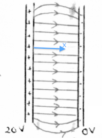 Consider the capacitor shown on the right,
which has a voltage of 20[V] between its (+) plate
and its (-) plate.
Using the (-) plate as a potential reference,
we can say that the voltage at (-) is 0[V],
and that the voltage at (+) is 20[V].
Assuming the material between the plates is uniform,
the voltage between the plates must vary continuously
as we go from one plate to the other.
The electric potential inside the capacitor is
\[
V(x) = 20 - \frac{20}{d}x,
\]
where $d$ is the plate separation and $x$ is a coordinate
which measures the distance from the (+) plate.
Check that $V(x)$ gives the correct potential at $x=0$ and
$x=d$.
The strength of the electric field inside the capacitor is therefore given by the derivative of the voltage with respect to $x$: \[ \vec{E}(x) = - \frac{d}{dx} V(x) = \frac{20}{d}. \qquad [\textrm{V}/\textrm{m}] \]
We generally report the units of electric field as $[\textrm{V}/\textrm{m}]$ instead of the equivalent $[\textrm{N}/\textrm{C}]$. This is an indicator of the fact that relationship $\vec{E}(x) = - \frac{d}{dx} V(x)$ is used more often than the relationship between $\vec{F}_e = q\vec{E}$ in practice.
Charging and discharging
The currents and voltages associated with the process of charging and discharging a capacitor can be described mathematically. In this section we will find the equation for the current $i_c(t)$ as a function of time by using principles from circuits and solving a simple differential equation.
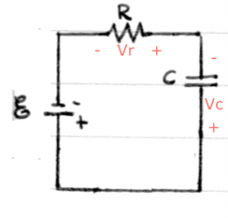 Consider a circuit which connects a battery, a capacitor and a resistor.
This is called an RC circuit.
The voltages across each of the elements have been indicated.
By Kirchhoff's voltage law (KVL) the voltage gains/drops
in this loop must add up to zero so we have:
\[
+ V_{\mathcal{E}} - v_c - v_r = 0.
\]
We now rewrite this equation in terms of the current $i(t)$ that will flow around the loop. We know that the voltage of a resistor is $v_r(t) = Ri(t)$ and we also know that $v_c(t)=\frac{1}{C}\int i(t) dt$, so the equation becomes: \[ + V_{\mathcal{E}} - \frac{1}{C}\int i(t) dt - Ri(t) = 0. \]
Now we take the derivative of this equation to obtain \[ + 0 - \frac{1}{C}i(t) - Ri'(t) = 0, \] where the first terms is zero because $V_{\mathcal{E}}$ is constant and the second term follows from the fundamental theorem of calculus (the derivative is the inverse operation of the integral).
We still haven't found $i(t)$ but we know that it must obey the following differential equation: \[ i'(t) = -\frac{1}{RC}i(t). \]
Can you think of any function $f(x)$ which is equal to the negative of its derivative up to a constant? The only function which has this property is of the form $f(x) = \alpha e ^{-\beta x}$, where $\beta > 0$ and $\alpha$ is an arbitrary constant.
By choosing the constant in the exponent appropriately, namely $\beta = \frac{1}{RC}$, we obtain the formula for the current in the circuit as a function of time \[ i(t) = \alpha e^{-\frac{t}{RC}}. \] Check that this function satisfies the differential equation $i'(t) = -\frac{1}{RC}i(t)$.
Now that we have the current $i(t)$ in the circuit, we can calculate the voltage of the capacitor by integration: \[ v_c(t) = \int i(t) dt = \beta e^{-\frac{t}{RC}} + \gamma, \] where $\beta=-\alpha RC$ and $\gamma$ is an arbitrary constant of integration.
We now discuss how to set the constants $\beta$ and $\gamma$ in the above equation so that it will describe the charging and discharging voltage of a capacitor.
Charging capacitor
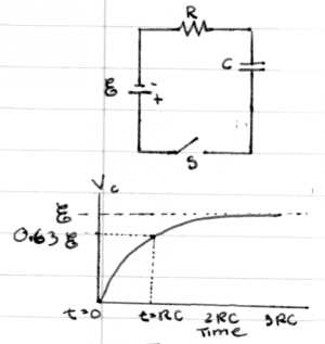 Consider capacitor of capacitance $C$ being charged
by a battery of $V_{\mathcal{E}}$ volts through a resistance
of $R$ ohms as illustrated in the circuit on the right.
We want to find the equation of
the voltage of the capacitor as a function of time.
We know that the general formula for the voltage in an RC circuit is given by \[ v_c(t) = \beta e^{-\frac{t}{RC}} + \gamma, \] so we have to just choose the constants $\beta$ and $\gamma$ appropriately by taking into account the boundary conditions. The first boundary condition is at $t=\infty$, when the capacitor will have fully charged to the voltage of the battery $V_{\mathcal{E}}$. Using this fact we can deduce that $\gamma=V_{\mathcal{E}}$ from the equation \[ v_c(\infty) = V_{\mathcal{E}} = \beta e^{-\frac{\infty}{RC}} + \gamma =\beta \times 0 + \gamma = \gamma. \]
The second boundary condition (we need two since there are two unknown constants) is that the capacitor starts completely discharged. Thus, when we close the switch at $t=0$, the initial voltage on the capacitor is $v_c(0)=0$. We can now use the equation \[ v_c(0) = 0 = \beta e^{-\frac{0}{RC}} + \gamma = \beta \times 1 + \gamma = \beta + \gamma \] and our previous findings that $\gamma=V_{\mathcal{E}}$ to deduce that $\beta=-V_{\mathcal{E}}$.
The function describing the voltage of a charging capacitor as function of time is therefore given by: \[ v_c(t) = V_{\mathcal{E}} - V_{\mathcal{E}} e^{-\frac{t}{RC}} =V_{\mathcal{E}} \left[ 1 - e^{-\frac{t}{RC}} \right]. \]
Recalling that $i_c(t) \equiv C\frac{dv_c(t)}{dt}$ we can also derive the current of the capacitor \[ i_c(t) = C\frac{d}{dt}\left[ V_{\mathcal{E}} - V_{\mathcal{E}} e^{-\frac{t}{RC}} \right] = \frac{V_{\mathcal{E}}}{R} e^{-\frac{t}{RC}}. \] The constant $\frac{V_{\mathcal{E}}}{R}=i_c(0)$, which we previously called $\alpha$, corresponds to the maximum charging current that will flow in the circuit.
Discharging capacitor
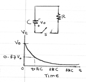 Consider now a capacitor charged to voltage $V_o$ which
discharges into a resistor of resistance $R$ starting at $t=0$,
when the switch is closed.
We start off from the general equation again \[ v_c(t) = \beta e^{-\frac{t}{RC}} + \gamma. \] The boundary conditions in this case are that the initial voltage $v_c(0)=V_o$ and the final voltage $v_c(\infty)=0$, which corresponds to the time when the capacitor has discharged completely. By plugging in the boundary conditions into the general equation we find that $\beta=V_o$ and $\gamma=0$. The equation for the voltage of a discharging capacitor is: \[ v_c(t) = V_o e^{-\frac{t}{RC}}. \]
We can also find the value of the capacitor current: \[ i_c(t) = C \frac{d}{dt} v_c(t) = -\frac{V_o}{R} e^{-\frac{t}{RC}}. \] The maximum discharge current is given by $-\frac{V_o}{R}=i_c(0)$. The negative sign indicates that the current is leaving the (+) plate of the capacitor.
In both of the above scenarios, the parameter $\tau=RC = \frac{1}{\beta}$ describes the time scale for the capacitor to charge or discharge. We call this quantity the time constant and measure it in seconds [s]. When charging, the time constant tells us how long it takes the capacitor to charge to $63\%=0.63=1-e^{-1}$ times its maximum voltage $V_{\mathcal{E}}$. When discharging, the time constant $\tau$ tells us how long it will take for the capacitor to reach $37\%=0.37=e^{-1}$ of its initial voltage $V_o$.
Explanations
Voltage continuity
The relationship between the current $i_c(t)$ and the voltage $v_c(t)$ is the defining features of a capacitors. More generally, we say that any circuit element is capacitive if the current of the device is proportional to the derivative of the voltage.
Capacitor energy derivation
We can equate the energy stored in a capacitor with the total energy consumed by the capacitor as while it charges up.
Consider some small amount of charge $dq$ which we want to add to the capacitor. The energy associated with moving this charge is given by $dE = dq v_c(t)$. This comes from the definition of power $\frac{dE}{dt} \equiv P(t) =i_c(t)v_c(t)$ and identifying the movement of charge $dq$ as the amount of current $i_c(t)=\frac{dq}{dt}$.
The total energy stored in the capacitor is calculated by taking the integral over the variable $q$. We sum up the individual contributions $dE$ for each of the $dq$s as the capacitor goes from $q=0$ to $q=Q$. \[ E = \int_{q=0}^{q=Q} v_c(q) \ dq = \int_{q=0}^{q=Q} \frac{q}{C} \ dq = \frac{1}{C} \frac{q^2}{2} \bigg|_{q=0}^{q=Q} = \frac{1}{2} \frac{Q^2}{C}. \] The other forms of the energy equation are obtained by using $Q=CV$.
Exercises
1. Capacitor charge
You are given a 5 [mF] capacitor and asked to produce a charging circuit which will charge the capacitors to 97% of the maximum voltage in 3[s]. What value should you use for the resistor?
2. Diff that for me will you?
Using a voltmeters, you observe that the voltage across a capacitor of capacitance $7$[$\mu$F] varies as the function $v_c(t) = 7\sin(120\pi t)$ [V]. What is the equation of current $i_c(t)$?
Magnetic field
If you were to put two current-carrying wires close to each other you will see that there will be a force between the wires. If the current is going in the same direction for both wires, then they will attract (buckle inwards), whereas if the currents are in opposite directions, the the wires will be pushed apart (tend to spread apart). This is the magnetic force. The powerful magnetic force is also what makes motors, generators and electromagnets work.
Recall that the electric force will exists between any two charged particles. Recall also how we invented the notion of an electric field $\vec{E}$ as an intermediary phenomenon. The story we told ourselves to explain the emergence of the electric force was as follows. One of the charges, say charge $Q$, creates an electric field $\vec{E}$ in space everywhere around it. The other charge (say $q$), will feel an electric force $F_e = q\vec{E}$ because of the electric field.
In this section we will follow a similar reasoning using a new intermediary concept. To explain the magnetic force between two current carrying wires, we will say that the current in the first wire is causing a magnetic field $\vec{B}$ everywhere in space and that the second current-carrying wire feels a magnetic force because of the magnetic field it is placed in.
A good way to learn about the properties of the magnetic field is to describe what are its causes and what are its effects. This is the approach we take below.
Concepts
General concepts:
- $I$: Electric current flowing in a wire or a loop.
- $\vec{B}$: Magnetic field strength and direction.
- $r$: Distance between two wires.
- $\vec{F}_b$: Magnetic force acting on another wire.
- $\mu_0$: the magnetic constant, or permeability of free space. It is equal to
$4\pi\times10^{-7}$ [Vs/Am] = $1.2566\times10^{-6}$ [H/m]=[N/A^2]
For solenoids we will have:
- $N$: Number of loops in a windings. Each turn of wire in the winding produces and
reacts to the magnetic field. A winding with $N$ turns produces a magnetic
  field that is $N$ times stronger than a single loop of wire.
* $L$: The length of a winding.
* $n \equiv N/L$: Is the winding density, how many turns per meter.
Currents
Each moving charges causes a magnetic field around it. However, the magnetic field created by a single moving charge is very small, so we will usually discuss magnetic fields created by currents.
Current is measured in Amperes [A], which is a equal to Coulombs per second [C/s]. Consider the following piece of wire with a current $3$[A] in it:
  a            b
  --------------
    I= 3 [A]
The above diagram makes no sense, since it does not specify the direction in whist the current is flowing. Let's fix it:
  a            b
  ------>-------
       I=3 [A]
That is better. When we say $I=3$[A], this means that there are 3[C] of charge flowing through this wire every second. The current enters the wire at $a$, and is confined to flow along the wire and thus it has to leave at point $b$.
If we say that the current is negative, this means that the current is flowing in the opposite direction of which the arrow points.
  a            b         a            b
  ------>-------    =    ------<-------
       I=-1 [A]              I=1 [A]
In the above diagram the current flows from $b$ to $a$, which is equivalent to saying that a negative current flows from $a$ to $b$.
Currents cause magnetic fields
The magnetic field $\vec{B}$ caused at some point $\vec{r}$ by a piece of wire of length $\ell$ carrying a current $I$ is given by \[ \vec{B} = \frac{k_b\ell I}{r^2} \hat{ I} \times \hat{r} = \frac{\mu_0}{4\pi}\frac{\ell I}{r^2} \hat{I} \times \hat{r}. \]
Don't freak out on me now. I know it looks complicated and there a arrows (vectors), cross products ($\times$), but you shouldn't worry. We will brake it down until it makes sense.
First the magnitude part: \[ |\vec{B}| = \frac{k_b \ell I}{r^2}, \] which doesn't seem quite so foreign no? I mean the electric field was the same story $|\vec{E}| = \frac{k_e Q}{r^2}$, where you have some cause $Q$ and the one-over-r-squared weakening plus some constant of proportionality $k_e=\frac{1}{4\pi \epsilon_0}$. The important thing to remember is that the cause of magnetic field is $\ell I$ the product of the current in the wire times the length of the piece of wire. The longer the wire is, the more magnetic field it will cause. This is the reason that people make “magnetic windings” with hundreds of turns instead of using a single loop.
As for the direction, yes we need to think about that for a moment:
- The direction of the magnetic field ${\hat B} = {\hat I} \times {\hat r}$
is perpendicular to both ${\hat I}$ and ${\hat r}$.
- If ${\hat I}$ and ${\hat r}$ point in the same direction then ${\hat B}=0$.
In general you will want to calculate not the magnetic field of a small piece, but of something more complicated. In this book (and in most E&M books), we will discuss three special cases of the magnetic field produced by:
- $\infty$-long straight wire.
- Loop of radius $R$.
- Solenoid of length $L$ with a total of $N$ windings.
Each of these configurations corresponds to a calculation involving an integral. When you see integral think “adding up the pieces” or “adding up the contributions”. We need an integral to calculate the total $\vec{B}$ field because different parts of the wire may contribute to the magnetic field unevenly. specific integral happens to be a vector integral. You don't need to understand the whole machinery of vector integration just yet, but you do need to know how to use the three formulas given below. If you are interested to see how we derived the formulas, you can check out the Derivations section below.
1. Magnetic field of a long wire
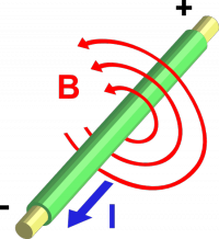 If you have take an infinitely long piece of wire and pass a current $I$ through it,
you will be creating a magnetic field $\vec{B}$ everywhere around the wire.
The magnetic field lines will be circulating around the wire.
This is how the magnetic field works.
It is important to get the right direction for the circulation. If you grab a piece of wire with your right hand in such a way that your thumb points in the direction of the current, then the magnetic field lines are circulating around the wire in the same direction as your fingers.
The further away you move from the wire the weaker the magnetic field $\vec{B}$ will get. If a point is $r$ meters away from the wire, the magnitude of the magnetic field at that point will be given by: \[ |\vec{B}| = \mu_0 \frac{I}{2\pi r} \]
This formula was discovered by André-Marie Ampère in 1826.
2. Magnetic field of a winding
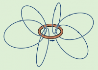 If you have a loop of wire that is carrying a current, then the strength of the magnetic field
in the centre is going to be:
\[
|\vec{B}_{centre}| = 2\pi R \frac{\mu_0}{4\pi} \frac{I}{R^2} = \frac{\mu_0I}{2R}.
\]
To get the direction of the magnetic field, you need use the right-hand rule again: grab the loop with your thumb pointed in the same direction of the current and then see which way your fingers point inside the loop.
3. Magnetic field of a solenoid
To create a stronger magnetic field, you can make loop the wire many times to create a winding. Each of the turns in the winding is going to contribute to the magnetic field inside and this way you can get some very strong magnetic fields.
Consider a winding that has $N$ turns and length $L$[m]. We call such a device a solenoid. The magnetic field $\vec{B}$ inside a solenoid is: \[ |\vec{B}| = \mu_0 n I, \] where $n$ is the winding density = number of windings per unit length $n=N/L$ [turns/m].
Effects of magnetic field
Force on a moving charge
A charge which is not moving feels no magnetic forces. Only when the charge is moving will it feel a magnetic force, and the faster the charge is moving the stronger the magnetic force will be.
The magnetic force that a charge $q$, moving with velocity $\vec{v}_q$ will field when it is passing through a magnetic field $\vec{B}$ is given by the formula: \[ \vec{F}_b = q (\vec{v}_q \times \vec{B}). \] Observe that the formula involves a cross product. This means that the force on the particle will be perpendicular to both the direction in which it is moving and the direction of the magnetic field. This is the second right-hand rule. Take your open right hand (don't curl your fingers) and place it so that your thumb points in the direction of the velocity and your fingers point in the direction of the magnetic field lines. The magnetic force will be in the direction of your palm.
It is interesting to point out that the magnetic force does zero work. This is because it always acts in a direction perpendicular to the displacement $\vec{d}$: \[ W_b = \vec{F}_b \cdot \vec{d} = 0. \] The magnetic force can change the direction in which the particle is travelling, but not make it go faster or slow it down. Indeed, a moving charged particle placed in a uniform magnetic field will turn around in a circle, because of the centripetal acceleration caused by the magnetic force.
More generally, we can write down the equation for the total electric + magnetic force that a charge feels. The combined force is called the Lorentz force, or electromagnetic force: \[ \vec{F}_{EM} = \underbrace{ q\vec{E} }_{\vec{F}_e} + \underbrace{ q (\vec{v}_q \times \vec{B}) }_{\vec{F}_b}. \]
Force on a current carrying conductor
Consider now a current $I$ flowing in a piece of wire of length $\ell$ placed in a magnetic field $\vec{B}$. The force on the piece of wire will be: \[ \vec{F}_b = \ell \vec{I} \times \vec{B}. \] Observe again that a cross product is used, so we need to use the second right-hand rule again to figure out the direction of the force.
Electromotive force
The two scenarios discussed above show how the magnetic field can produce a mechanical force on an object. Magnetic fields can also produce electromotive forces inside a given circuit, that is, the magnetic field can cause (we usually say induce to sound fancy) a voltage inside the circuit and made a current circulate. This phenomenon is called Faraday's law of induction and will be the subject of the next section.
Explanations
Some of you may feel cheated by this chapter. Here I am telling you to memorizing five formulas without telling you where they come from. Let's fix that.
Ampere's law
One of the most important laws for magnetism is Ampere's law. Like Gauss' law electromagnetism, it is not so much a law as a principle from which many laws can be derived.
The statement involves some area of space $A$ with a total current $I_{in}$ passing through that area. Let the closed path $\mathcal{C}$ correspond to the circumference of the area $A$ (the boundary). If you integrate the strength of the magnetic field along the path $\mathcal{C}$ (this is called the circulation), you will find that it is proportional to the total amount of current flowing inside the loop: \[ \oint_{\mathcal{C}} \vec{B} \cdot d\vec{s} = \mu_0 I_{in}. \] Like Gauss' law, Ampere's law simply tells us that we can do the accounting for magnetic phenomena in two different ways: either we calculate the circulation of the magnetic field along the boundary (the path $\mathcal{C}$) or we calculate the total current flowing inside.
The formula of for the strength of the $\vec{B}$ field around an infinitely long wire comes from Ampere's law. Let $\mathcal{C}$ be an imaginary circle of radius $r$ centred on the wire. The $\vec{B}$ field will be constant in magnitude and always pointing along the path of integration so we will get: \[ \oint_{\mathcal{C}} \vec{B} \cdot d\vec{s} = \int_{0}^{2\pi} |\vec{B}| \ r d\theta = |\vec{B}| 2\pi r = \mu_0 I_{in}. \] Solve for $|\vec{B}|$ to obtain the formula for the $\infty$-long wire.
The Biot–Savart law
More generally, to calculate the magnetic field produced by some arbitrarily shaped wire $\mathcal{L}$ that is carrying a current $I$ we use the following formula: \[ \vec{B}(\vec{r}) = \int_\mathcal{L}\frac{\mu_0}{4\pi} \frac{I}{|\vec{r}|^2} d\mathbf{l} \times {\hat r}, \] which tells you how strong the magnetic field $\vec{B}$ will be at a point $\vec{r}$. The cause of this field is the current $I$, that is flowing in the length of wire $\mathcal{L}$. The expression is an integral which tells us that we should split the entire length of the wire into little pieces of length $dl$ and add up all their magnetic contributions.
We need an integral because different parts of the wire may contribute to the magnetic field unevenly. This happens to be a vector integral, which you probably have not seen before, and I don't think you need to understand the whole machinery just yet. When you see integral think “adding up the pieces”.
Applications
Every time you have a moving charge, there will be a magnetic field $\vec{B}$. Here is a list of real-world phenomena that involve magnetic fields. In each case, when we analyze what is going on we see that some moving charge is causing the magnetic fields.
- light consists of little bundles of energy called photon.
A photon is a wave of EM energy produced by an excited
  electron dropping to a lower energy level in some atom.
* permanent magnets (like a fridge magnet) exhibit magnetic properties
  because of the many tiny loops of "electron flow" circling around Fe atoms.
* The magnetic field of the earth is caused by the flow of charged
  magma in the earth's core.
And Mankind saw that magnetic field was good, and decided to make more of it. If moving charges create lots of magnetic field, then let's get lots of charge moving (a current $I$) and then we will have lots of magnetic field!
The following are some practical applications of the magnetic fields and the magnetic forces they produce:
- electromagnet = used to lift cars in the scrap yard, to lock the doors of buildings and to make particles spin around.
- magnetic field inside a motor = used to convert electric energy into mechanical work (think the motor of your elevator, or the one that drops the window down in your car).
- magnetic field inside a generator = used to convert mechanical work into electric energy (think you car's alternator).
- MRI = magnetic resonance imaging allows us to distinguish different molecules
in the human body by using carefully chosen oscillating magnetic fields.
Examples
Links
[ Nice pictures of magnetic fields ]
http://en.wikipedia.org/wiki/Magnetic_field
http://web.mit.edu/8.02t/www/802TEAL3D/visualizations/magnetostatics/index.htm
[ An expandable summary of the magnetic field ]
http://www.telescopictext.org/text/pFjkqQY9bmfvQ
[ Good illustrations of the first right-hand rule ]
http://hyperphysics.phy-astr.gsu.edu/hbase/magnetic/magcur.html
Magnetic induction
In the previous section we learned about the magnetic field, how it is caused by current carrying wires and its effects on other current carrying wires. In this chapter we will learn how a changing magnetic fields can produce an electromotive force – how changing currents in one wire can induce a current in another wire.
Note that magnetic field has to be changing in order to produce induced voltages and an induced currents. A constant currents produces a constant magnetic field and a constant magnetic fields does not induce currents. This is a very important to keep in mind.
In this section we will study Faraday's law of induction. It states that any change in the total magnetic field flowing through some winding will cause an induced current to flow in the winding as a result. This is a special case of the more general Le Chatelier principle since the induced current will flow in such a direction as to produce a oppose magnetic field and counter act the external change.
Concepts
- $\mu_0$: the magnetic constant, or permeability of free space. It is equal to
$4\pi\times10^{-7}$ [Vs/Am] = $1.2566\times10^{-6}$ [H/m]=[N/A^2]
- $\vec{B}$: Magnetic field strength and direction.
- $\mathcal{E}\equiv V_{\mathcal{E}}$: Induced electric potential (induced voltage)
in the winding. It is also known as the electromotive force.
- $I_{\mathcal{E}}$: Induced electric current. The induced current in a winding of
resistance $R$[$\Omega$] will be $I_{\mathcal{E}}=\mathcal{E}/R$.
- $S$: some surface in space. ex: $S$=the area enclosed by a loop of wire.
- $\Phi_S$=The magnetic flux through $S$, i.e., how much magnetic
filed $B$ passes through the surface $S$. We have $\Phi_S = \vec{B} \cdot \vec{S}$,
  where $\vec{S}$ is the oriented surface area.
* $N$: Number of loops in a winding. Each turn of wire in the winding produces and
  reacts to the magnetic field. The induced voltage in a winding with $N$ turns
  is $N$ times stronger than that induced in a single loop of wire.
Formulas
Magnetic flux
Consider the surface $S$ and let $\hat{n}$ be a vector that is perpendicular to the surface (the normal vector). The directed surface is given by $\vec{S}=S\hat{n}$.
The magnetic flux is given by: \[ \Phi_S = \vec{B} \cdot \vec{S} = |\vec{B}|S \cos \theta, \] where $\theta$ is the angle between the normal vector of the surface $S$ and the orientation of the magnetic field. The flux measures of how many magnetic field lines flow through the surface. If the magnetic field flows perpendicularly to the surface then $\theta=0$ and $\Phi_S = |\vec{B}|S$. On the other hand, if the magnetic field is parallel to the surface, then $\theta=90^\circ$ and there is zero magnetic flow through the surface.
Faraday's law of induction
Consider a loop of wire and let $S$ represent the area enclosed by this loop. Faraday's law states that any change in the magnetic flux through that loop will produce an induced voltage (an electromotive force) on all electrons in the wire. The magniture of this induced voltage is given by the formula: \[ \mathcal{E} = - \frac{d \Phi_S}{dt}. \] The negative sign is there to remind you that the induced voltage will always act in a opposite direction to the change in the flux.
Example: Changing B
Suppose you have a loop of wire with area $A=5$[m$^2$] in a place this loop in a location where an upward magnetic field exists, which is slowly increasing in time: \[ \vec{B}(t) = (0,0, 3t) = 3t \hat{k}. \] Every second the magnetic field will become stronger by $3$[T].
Faraday's law tells us that the changing magnetic field will induce a voltage (electromotive force) in the loop that is equal to \[ \mathcal{E} = - \frac{d \Phi_S}{dt} = - \frac{d}{dt} \left( \vec{B}(t)\cdot\vec{A} \right) = - \frac{d}{dt} \left( 3t \hat{k} \cdot A\hat{k} \right) = A \frac{d}{dt}\left( 3t \right) = 15 [V]. \] The effects of the induced voltage $\mathcal{E}$ in the loop is equivalent to connecting a $15$[V] battery somewhere in the loop.
If the electric resistance of the loop of wire is 10[$\Omega$], then the induced current will be 1.5[A]. This current will flow in the clockwise direction when looked from above. This is because the induced current is trying to counteract the increasing and upward pointing magnetic field by causing a downward magnetic field.
Observe that the value of the magnetic field was not important in this context: only the derivative of the field mattered. The answer would have been the same if we had $\vec{B}(t) = (3t + 3000)\hat{k}$, because the derivative of a constant is zero.
Generators
Consider now a constant magnetic field $\vec{B}$ and wire winding of area $A$[m$^2$] mounted on an axis so that it can rotate. Such a construction could serve as a rudimentary electric generators: a device which transforms rotational mechanical energy into electric energy.
The magnetic flux through the winding will be given by: \[ \Phi_S = N \vec{B} \cdot \vec{A} = NBA \cos(\theta), \] where $N$ is the number of turns in the winding and $\theta$ describes the orientation of the winding relative to the constant magnetic field.
If we use an external force to make the winding rotate at a constant speed $\omega$ then the magnetic flux as a function time will be: \[ \Phi_S(t) = NBA \cos(\omega t + \theta_0). \]
The induced voltage that we would be able to read if we were to put a voltmeter on the two ends of the turning winding would be: \[ \mathcal{E}(t) = - \frac{d \Phi_S(t) }{dt} = - \frac{d}{dt}\left( NBA \cos(\omega t + \theta_0) \right) = NBA\omega \sin(\omega t + \theta_0). \]
This is an alternating voltage, that keeps changing from positive to negative depending on the relative orientation of the loop in the magnetic field. This is how Hydro Quebec generates power. With big generators.
Electric motor
A generator can also be used backwards: the same device can also be used to convert electric energy into mechanical energy. Used in that direction, the rotating winding construction is called an electric motor.
A motor has two parts. The stator, which in our case is the constant background magnetic field $\vec{B}$ and a rotor, which is our rotating winding.
If we use electric energy to make a current flow in the winding, then the winding will produce its own magnetic field and the interaction between the two B-fields will cause the winding to turn.
Transformers
If you put two windings close to each other and put an make and alternating current flow in one of the windings, we will immediately see an induced alternating current in the second winding. This device is called a transformer. We will learn about these in more detail in the chapter on alternating currents.
Self inductance
Consider a solenoid of cross section area $A$ and winding density $n = N/L$ which has a current $i(t)$ flowing in the wire.
We learned in the last section that a current $i(t)$ flowing in the solenoid will produce a magnetic field inside the device and we know that the formula is given by: \[ |\vec{B}| = \mu_0 n i(t). \]
We learned in this section that any winding will react to a change in the magnetic flux through it by producing an induced voltage. Since a solenoid is a winding, so it will react to any changes in the magnetic field which would appear if the current were changing in time. The formula for the induced voltage is: \[ \mathcal{E} = - \frac{d \Phi_S(t) }{dt} = - \frac{d (AN|\vec{B}|) }{dt}, \] where we used the fact that the magnetic field everywhere inside an inductor is constant and that each of the $N$ windings contribute to the total induced voltage.
Combining these formulas we see that \[ \mathcal{E} \equiv v(t) = - \frac{d (AN|\vec{B}|) }{dt} = - \underbrace{AN\mu_0 n}_L \frac{d i(t)}{dt} = - L \frac{d i(t)}{dt}, \] where we have lumped together all the constants into a single one $L$.
This solenoid, and in general all windings, exhibit this phenomenon of self-inductance where the chaining current in the winding cause an induced voltage.
In circuits we call such devices inductors and they are in some sense the dual of the capacitor in which it was the changing voltage that caused a current. The constant $L$ is called the inductance or self-inductance of the device.
Examples
Example 1: Area changing
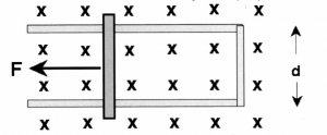 Consider the external force $\vec{F}$ that is dragging
the bar along with velocity $\vec{v}$. If the magnetic field
everywhere is given by $\vec{B}$ and points into the page.
What is the change of flux $\frac{d \Phi_S(t) }{dt}$ ?
What is the induced voltage? Will the induced current flow in the clockwise or counter-clockwise direction when looked from above?
Example 2: Strength changing
If the magnet is moved away from the loop, what will be the induced current in the loop?
- none
- a
- b
explain
Discussion
Links
[ More on Faraday's law of from HyperPhysics ]
http://hyperphysics.phy-astr.gsu.edu/hbase/electric/farlaw.html
http://hyperphysics.phy-astr.gsu.edu/hbase/magnetic/fluxmg.html
[ Ilustrations of magnetic induction ]
http://web.mit.edu/8.02t/www/802TEAL3D/visualizations/faraday/index.htm
End matter
Conclusion
I would like to go on telling you about other math and physics stuff, but at some point we have to take a brake. This time is now.
We managed to cover a lot of ground in terms of topics and concepts in a relatively small textbook. We reviewed high school math and discussed calculus and mechanics in depth. Above all, we presented the math and physics material in an integrated manner.
It will sound a little cheesy, but it is the truth so I will go ahead and say it.
I am writing this book for you so if you liked/hated it, be sure to send me feedback.
Feedback is very important for me so I know how to adjust the writing,
the content and the attitude in the book.
Please take the time to drop me a line and let me know what you think about this book.
My email address is: ivan.savov@gmail.com.
You can also find me on twitter: http://twitter.com/minireference
and Facebook http://facebook.com/pages/Math-and-Physics-Minireference/189157377884715.
There is also the company blog at http://minireference.com/blog/ where I
discuss the business side of things.
