The page you are reading is part of a draft (v2.0) of the "No bullshit guide to math and physics."
The text has since gone through many edits and is now available in print and electronic format. The current edition of the book is v4.0, which is a substantial improvement in terms of content and language (I hired a professional editor) from the draft version.
I'm leaving the old wiki content up for the time being, but I highly engourage you to check out the finished book. You can check out an extended preview here (PDF, 106 pages, 5MB).
Lenses
Definitions
To understand how lenses work, we imagine again some test object. (an arrow) and the test image it forms.
- $d_o$: The distance of the object from the lens.
- $d_i$: The distance of the image from the lens.
- $f$: The focal length of the lens.
- $h_o$: The height of the object.
- $h_i$: The height of the image.
- $M$: The magnification $M=h_i/h_o$.
When drawing lens diagrams, we use the following representative rays:
- $R_\alpha$: A horizontal incoming ray which gets redirected towards
the focus after it passes through the lens.
- $R_\beta$: A ray that passes through the focus and gets redirected horizontally
after the lens.
- $R_\gamma$: A ray that passes exactly through the centre of the lens
and travels in a straight line.
Formulas
\[ \frac{1}{d_o} + \frac{1}{d_i} = \frac{1}{f} \]
\[ M = \frac{h_i}{h_o} = \frac{|d_i|}{|d_o|} \]
Examples
Visual
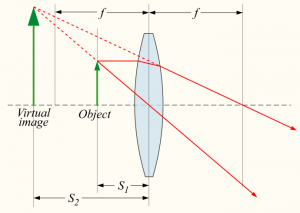
Fist consider the typical magnifying glass situation. You put the object close to the lens, and looking from the side, the object will appear magnified.
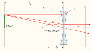
A similar setup with a diverging lens. This time the image will appear to the observer to be smaller than the object.
Note that in the above two examples, if you used the formula you would get a negative $d_i$ value since the image is not formed on the “right” side. We say the image is virtual.
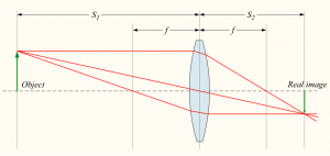
Now for an example where a real image is formed:
In this example all the quantities $f$, $d_o$ and $d_i$ are positive.
Numerical
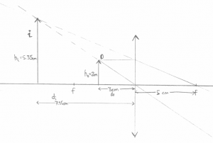
An object is placed at a distance of 3[cm] from a magnifying glass of focal length 5[cm]. Where will the object appear to be?
You should really try this on your own. Just reading about light rays is kind of useless. Try drawing the above by yourself with the ruler. Draw the three kinds of rays: $R_\alpha$, $R_\beta$, and $R_\gamma$.
Here is my drawing.
Numerically we get \[ \frac{1}{d_o} + \frac{1}{d_i} = \frac{1}{f}, \] \[ \frac{1}{3.0} + \frac{1}{d_i} = \frac{1}{5.0}, \] \[ d_i = 1.0/(1.0/5.0 - 1.0/3.0) = -7.50 \text{[cm]}. \]
As you can see, drawings are not very accurate. Always trust the formula for the numeric answers to $d_o$, $d_i$ type of questions.
Multiple lenses
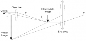
Imagine that the “output” image formed by the first lens is the “input” image to a second lens.
It may look complicated, but if you solve the problem in two steps (1) how the object forms an intermediary image, and (2) how the intermediary image forms the final image you will get things right.
You can also trace all the rays as they pass through the double-lens apparatus:
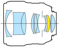 We started this chapter talking about real cameras, so I want to
finish on that note too. To form a clear image, with variable focus and
possibly zoom functionality, we have to use a whole series of lenses,
not just one or two.
For each lens though, we can use the formula and calculate the effects of that lens on the light coming in.
Note that the real world is significantly more complicated than the simple ray picture which we have been using until now. For one, each frequency of light will have a slightly different refraction angle, and sometimes the lens shapes will not be perfect parabolas, so the light rays will not be perfectly redirected towards the focal point.
Discussion
Fresnel lens
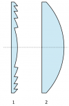 Thicker lenses are stronger. The reason is that the curvature
of a thick lens is bigger and thus light will be refracted more
when it hits the surface.
The actual thickness of the lens is of no importance.
The way rays get deflected by lenses only depends on the angles of
incidence. Indeed, we can cut out all the middle part
of the lens and leave a highly curved surface parts.
This is called a Fresnel lens and it is used in car headlights.
